Reciprocating pump assembly

a pump and assembly technology, applied in the direction of machines/engines, liquid fuel engines, positive displacement liquid engines, etc., can solve the problems of damaging the power end seal, and contaminating the power end housing

Active Publication Date: 2014-04-29
SPM OIL & GAS INC
View PDF157 Cites 135 Cited by
  • Summary
  • Abstract
  • Description
  • Claims
  • Application Information

AI Technical Summary

Benefits of technology

[0035]According to a sixth aspect, there is provided a reciprocating pump assembly having a power end housing and a fluid end housing and a cylinder disposed within the power end. A plunger assembly reciprocates between the power end housing and the fluid end housing of the pump assembly, the plunger assembly having a crosshead, a first section limited to movement within the power end and a second section moveable within the fluid end housing. The pump assembly includes a means for retaining the first and second sections to the crosshead, the retaining means extending through the first section and at least partially through the second section, the retaining means compressing the first and second sections against the crosshead to securely fasten the second section and the first section to the crosshead.

Problems solved by technology

Thus, in order to meet these width requirements, pumps have been designed with reduced sizes (i.e., the pumps are shortened, mounted closer together, designed with shorter stroke lengths, etc.), which oftentimes results in damage to the power end seal and contamination of the power end housing.
For example, due to the shortened length of the pumps, fluid proppant oftentimes propagates along the plunger from the fluid end housing and contacts the power end seal, thereby damaging the power end seal and eventually contaminating the power end housing.
Furthermore, such plungers and associated mounting component are susceptible to fatigue failure and / or high bending moments, which decreases the reliability of such pump assemblies.

Method used


Image

  • Reciprocating pump assembly
  • Reciprocating pump assembly
  • Reciprocating pump assembly

Examples


Embodiment Construction

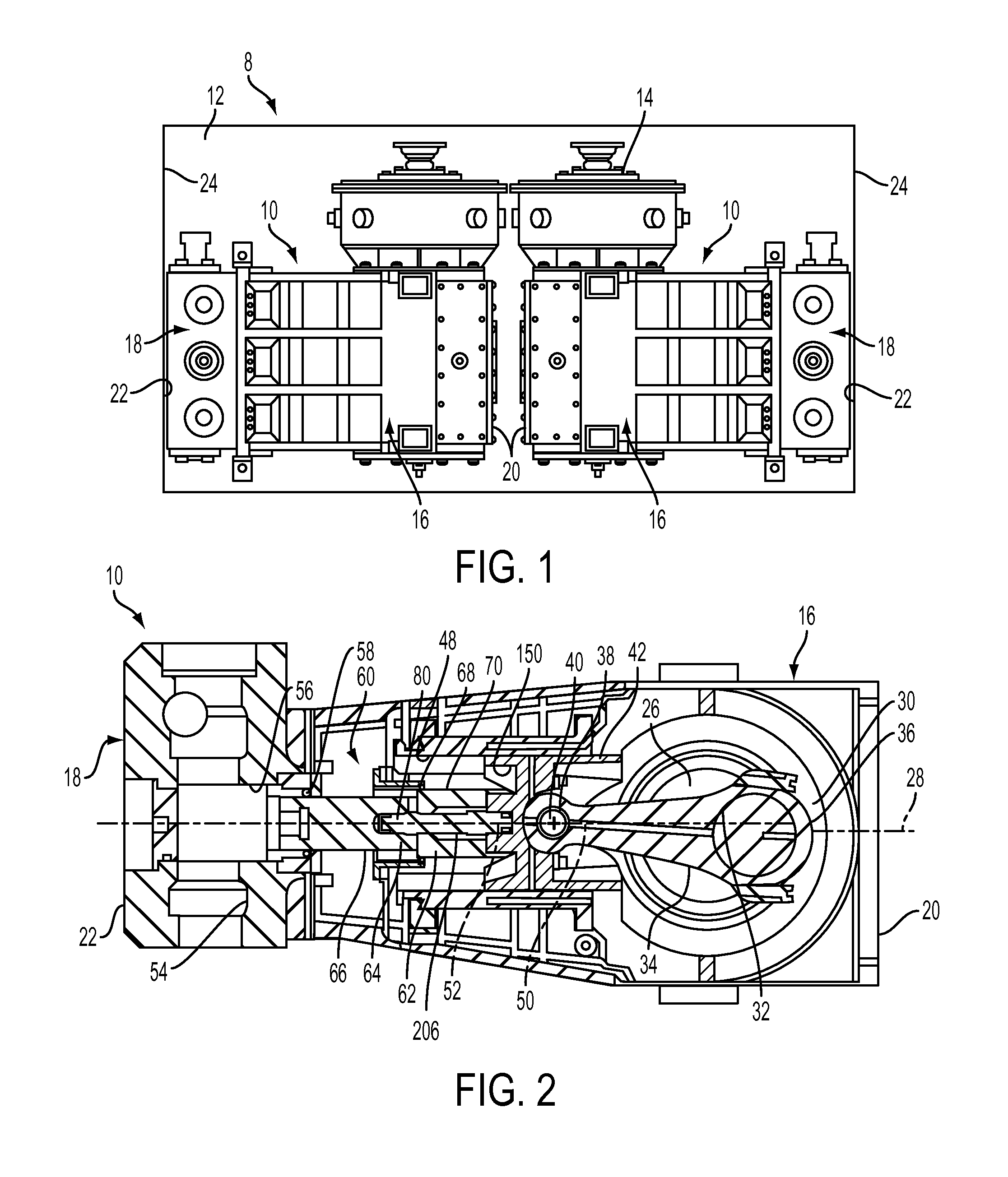
[0043]FIG. 1 is an illustration of a back to back pump assembly 8 according to one or more aspects of the present disclosure. In particular, FIG. 1 depicts a pair of pumps 10, such as, for example, reciprocating plunger pumps or a well service pumps, which are mounted in a back-to-back configuration on a platform 12 (e.g., a skid, truck bed, trailer, etc.). In the embodiment illustrated in FIG. 1, the pumps 10 are identical pumps although they may be of different types and / or inverted relative to one another. The pumps 10 together with a prime mover (not illustrated) are mounted on the platform 12 to provide a portable self-contained pumping assembly 8 that is easily transported to and from a well site for pumping operations. The prime mover is, for example, an electric motor or an internal combustion engine (e.g., a diesel engine) connected to a gear reducer 14 for reciprocating the pump assembly 10. In the embodiment illustrated in FIG. 1, the pumps 10 are depicted as triplex pump...


PUM


Abstract

A reciprocating pump assembly having a power end housing and a fluid end housing and a cylinder having at least a portion within the power end. A plunger assembly reciprocates between the power end housing and the fluid end housing of the pump assembly, the plunger assembly having a crosshead, a first section limited to movement within the power end and a second section moveable within the fluid end housing. The pump assembly also includes a seal housing disposed within the cylinder, the seal housing having a proximal end adjacent an entrance to the cylinder, and a distal end disposed within the cylinder. A power end seal is secured to the seal housing proximate the distal end and a fluid end seal is disposed within the fluid end housing. The power end seal sealingly engages an outer surface of the first section and the fluid end seal sealingly engages an outer surface of the second section such that during the reciprocating movement of the plunger assembly, fluid end proppant is deterred from contaminating the outer surface of the first section and thus, contaminating the power end seal.

Description

TECHNICAL FIELD[0001]This invention relates to pump assemblies for well servicing applications, and in particular, to pump assemblies having two pumps mounted back-to-back on a platform for transport to and from a well-site.BACKGROUND OF THE DISCLOSURE[0002]In conventional drilling and completion of a well, cement is pumped into an annulus between a wellbore casing and the subterranean surface. Once the cement is sufficiently set, the cement can support and protect the casing from exterior corrosion and pressure changes.[0003]A reciprocating or positive displacement pump is typically used for cementing and wellbore treatments and has three or five reciprocating element. The reciprocating pump includes a power end and fluid end section. The power end of the pump includes a housing having a crankshaft mounted therein. A connecting rod is connected to the crankshaft. The connecting rod includes a crankshaft end and a crosshead end. The crosshead end of the connecting rod is located in ...

Claims


Application Information

Patent Timeline
Patent Type & Authority Patents(United States)
IPC IPC(8): F16J15/18
CPCF04B53/14F04B53/16F04B53/147F16J15/18F04B39/0022F04B39/0005
Inventor DILLE, MARK C.ARNOLDY, DAVIDFREED, WESLEY D.
Owner SPM OIL & GAS INC
Why Eureka
Try Eureka