
High gain, high voltage power amplifier

a high-voltage, power amplifier technology, applied in the direction of amplifiers, electroluminescent amplifiers, amplifiers with semiconductor devices/discharge tubes, etc., can solve the problem of difficulty in achieving multiple power envelopes, and achieve the effect of high impedance and high impedan

Active Publication Date: 2014-05-06
KEITHLEY INSTRUMENTS INC
View PDF3 Cites 5 Cited by
  • Summary
  • Abstract
  • Description
  • Claims
  • Application Information

AI Technical Summary

Benefits of technology

The patent describes an opto-isolated amplifier and method that uses a pair of opto-isolators to create gain between an input and an output. An amplification stage with a high impedance is connected to the opto-isolators to receive the difference current. The opto-isolators are designed to direct the current to the amplification stage, creating a high-impedance input. The amplified output is then directed through a feed forward capacitor to achieve the desired amplification. The technical effect of this design is to improve the stability and accuracy of the signal amplification process.

Problems solved by technology

Existing techniques also make it very difficult to achieve multiple power envelopes as is typically required of a source measurement unit.

Method used


Image

  • High gain, high voltage power amplifier
  • High gain, high voltage power amplifier
  • High gain, high voltage power amplifier

Examples


Embodiment Construction

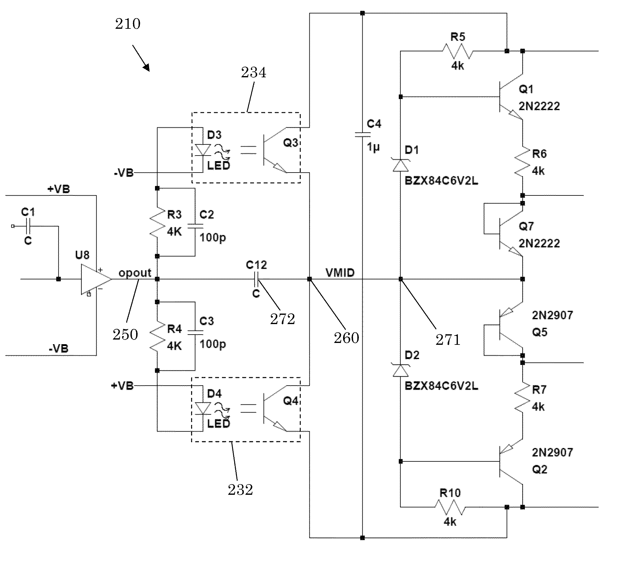
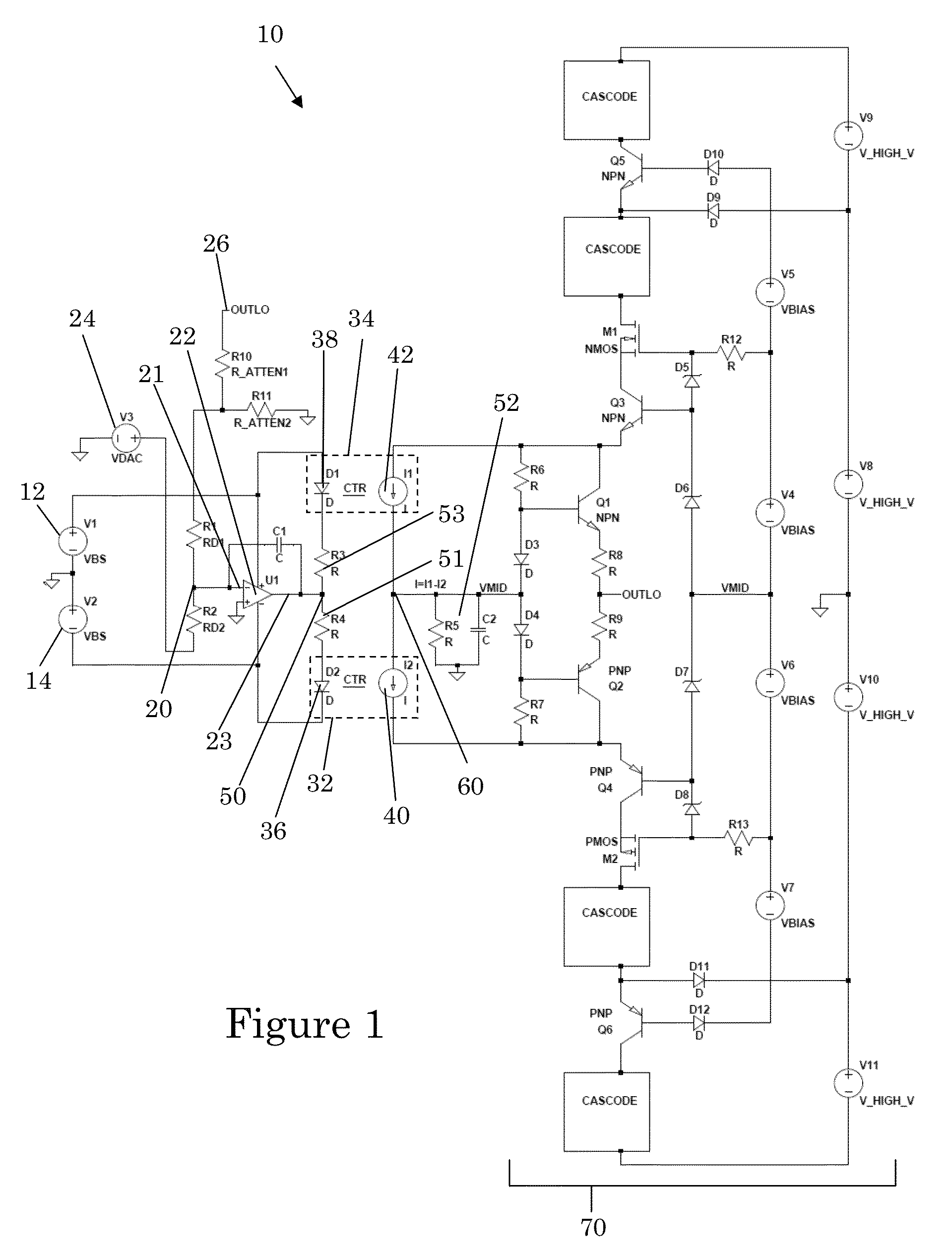
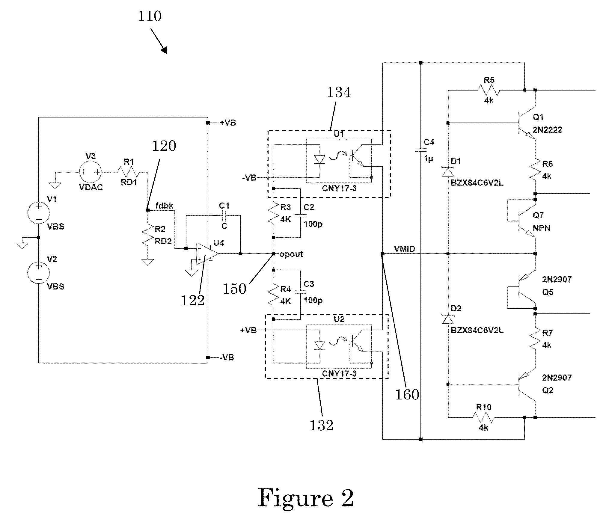
[0017]Disclosed herein is an apparatus and method that provides high gain amplification with isolation from input to output. This enables much larger signal voltages on the output than typical input circuit components can withstand. The apparatus and methods disclosed herein allows a low voltage circuit signal be amplified to a high voltage, e.g., 300V / V, opto-electronically, without the need of a complicated intermediate signal translation circuit. Such circuitry is useful in products like the Keithley 2600 family where all control signals are low voltage and are referenced to ground and where it is necessary to produce higher voltages.

[0018]Prior designs achieve this goal with topologies that include a string of intermediate transistors to translate the low voltage signals to high voltage. This is done on the Keithley model 2612 where there is a 200V output stage. This type of design costs additional parts and increased power dissipation to power this intermediate stage.

[0019]A go...


PUM


Abstract

An opto-isolated amplifier and method are disclosed. The amplifier includes an input node configured to receive an input to be amplified. A pair of opto-isolators are coupled between an input node and an output node. The opto-isolators are configured to create gain between the input node and the output node. An amplification stage is coupled to the opto-isolators. The amplification stage includes an input coupled to the output node and an output configured to generate an amplified output. The opto-isolator outputs may be configured to generate a difference current. The input of the amplification stage may have a high impedance compared to an impedance at the output node, the difference current being directed at the high input impedance input of the amplification stage to generate a gained voltage.

Description

CROSS-REFERENCE TO PRIOR FILED APPLICATIONS[0001]This application claims priority to earlier filed U.S. provisional application No. 61 / 621,784, filed Apr. 9, 2012, which is incorporated herein in its entirety.FIELD OF INVENTION[0002]This invention relates generally to power amplifiers and, more particularly, to power amplifiers capable of high gain and high voltage output from low voltage input.BACKGROUND[0003]Source measure units (SMU) are used to make precision measurements in many fields, including the testing of semiconductor products. Source measure units force either a voltage or a current and then respectively measure a resulting current or voltage. Existing high voltage amplifier circuits incorporated into an SMU typically use voltage translation circuits to achieve gain from low voltage inputs to high voltage outputs. Existing techniques also make it very difficult to achieve multiple power envelopes as is typically required of a source measurement unit. For example, consid...

Claims


Application Information

Patent Timeline
Patent Type & Authority Patents(United States)
IPC IPC(8): H03F17/00
CPCH03F3/085H03F3/211H03F2200/411H03F3/3069
Inventor CAWLEY, KEVIN, G.
Owner KEITHLEY INSTRUMENTS INC
Learn More