System and method for generating three dimensional images using lidar and video measurements

Active Publication Date: 2014-05-06
AEVA INC
View PDF126 Cites 43 Cited by
  • Summary
  • Abstract
  • Description
  • Claims
  • Application Information

AI Technical Summary

Benefits of technology

[0007]Various implementations of the invention combine measurements generated by a a lidar system with images generated by a video system to resolve a six degrees of freedom trajectory that describes motion of a target. Once this trajectory is resolved, an accura

Problems solved by technology

Unfortunately, the pre-specified initial model places significant restraints on the ability of the systems to combine lidar measurements with the video image and as a result, the three dimensional image is seldom sufficient for purposes

Method used


Image

  • System and method for generating three dimensional images using lidar and video measurements
  • System and method for generating three dimensional images using lidar and video measurements
  • System and method for generating three dimensional images using lidar and video measurements

Examples


Embodiment Construction

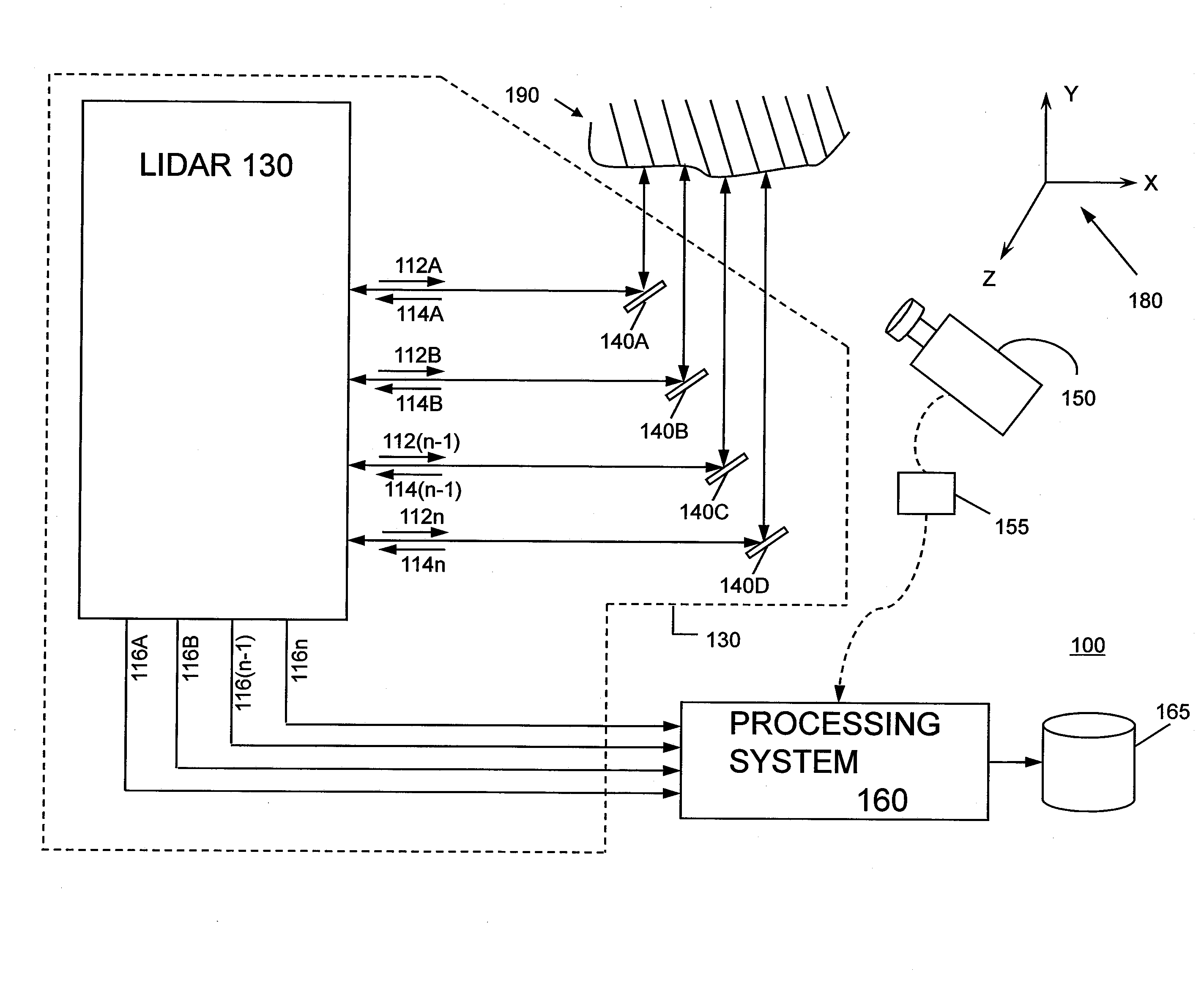
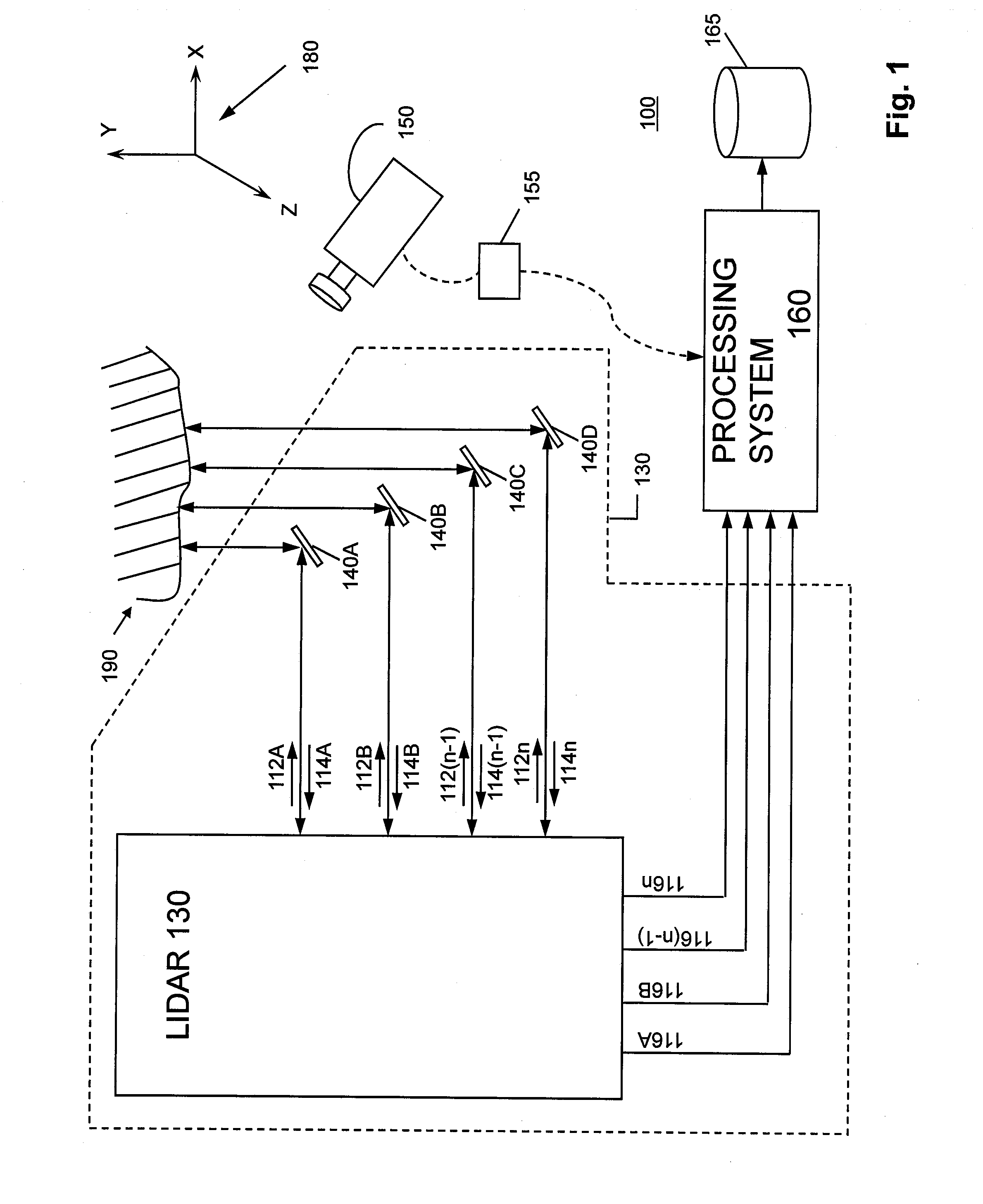
[0026]FIG. 1 illustrates a combined lidar and video camera system 100 according to various implementations of the invention. Various implementations of the invention utilize synergies between lidar measurements and video images to resolve six degrees of freedom for motion of a target to a degree not otherwise possible with either a lidar or video camera alone.

[0027]Combined system 100 includes a lidar subsystem 130, a video subsystem 150, and a processing system 160. As illustrated, lidar subsystem 130 includes two or more lidar beam outputs 112 (illustrated as a beam 112A, a beam 112B, a beam 112(n-1), and a beam 112n); two or more reflected beam inputs 114 each corresponding to one of beams 112 (illustrated as a reflected beam 114A, a reflected beam 114B, a reflected beam 114(n-1), and a reflected beam 114n); two or more lidar outputs 116 each associated with a pair of beam 112 / reflected beam 114 (illustrated as a lidar output 116A associated with beam 112A / reflected beam 114A, a ...


PUM


Abstract

A system uses range and Doppler velocity measurements from a lidar system and images from a video system to estimate a six degree-of-freedom trajectory of a target. The system estimates this trajectory in two stages: a first stage in which the range and Doppler measurements from the lidar system along with various feature measurements obtained from the images from the video system are used to estimate first stage motion aspects of the target (i.e., the trajectory of the target); and a second stage in which the images from the video system and the first stage motion aspects of the target are used to estimate second stage motion aspects of the target. Once the second stage motion aspects of the target are estimated, a three-dimensional image of the target may be generated.

Description

CROSS-REFERENCE TO RELATED APPLICATIONS[0001]This application claims priority to U.S. Provisional Patent Application No. 61 / 154,207, which was filed on Feb. 20, 2009, and is incorporated herein by reference as if reproduced below in its entirety.FIELD OF THE INVENTION[0002]The invention is generally related to combining lidar (i.e., laser radar) measurements and video images to generate three dimensional images of targets, and more particularly, to resolving a six-degree-of-freedom trajectory associated with a moving target via the lidar measurements and the video images to obtain a motion stabilized three dimensional image of the target.BACKGROUND OF THE INVENTION[0003]Various conventional systems attempt to merge lidar measurements and video images to obtain three dimensional images of targets. Typically, these conventional systems require some pre-specified initial model of the target in order to combine lidar measurements with the video image to form a three dimensional image.[0...

Claims


Application Information

Patent Timeline
IPC IPC(8): G01C3/08G01S7/491G01S17/34G01S17/86G01S17/89
CPCG01C11/02G01S17/66G01S17/023G01S17/89G01S17/42G06T7/70G06T7/246G01S7/4815G01S7/491H04N13/211G01S17/58G01S17/34G01S17/86G06V20/46G06V40/20G06T7/60G06T7/74G06T7/248G06T2207/10028
Inventor SEBASTIAN, RICHARD LEEZHELEZNYAK, ANATOLEY T.
Owner AEVA INC
Why Eureka
Try Eureka