Apparatus and method for aircraft engine core exchange

a technology for aircraft engines and components, applied in the direction of machines/engines, manufacturing tools, forging/pressing/hammering apparatus, etc., can solve the problems of increasing the amount of labor and time involved in exchanging aircraft engine components, affecting the accuracy and efficiency of engine fan modules, and many prior art methods for installing engine components that do not accurately and efficiently align engine cores with engine fan modules

Active Publication Date: 2014-05-13
SPIRIT AEROSYSTEMS
View PDF16 Cites 12 Cited by
  • Summary
  • Abstract
  • Description
  • Claims
  • Application Information

AI Technical Summary

Problems solved by technology

However, these engine core transport systems are generally large and require removal of various nacelle components in order to insert or remove the engine core.
This increases the amount of labor and time involved in exchanging an aircraft engine core.
Furthermore, many prior art methods for installing engine cores do not accurately and efficiently align the engine cores with the engine fan modules.

Method used


Image

  • Apparatus and method for aircraft engine core exchange
  • Apparatus and method for aircraft engine core exchange
  • Apparatus and method for aircraft engine core exchange

Examples


Embodiment Construction

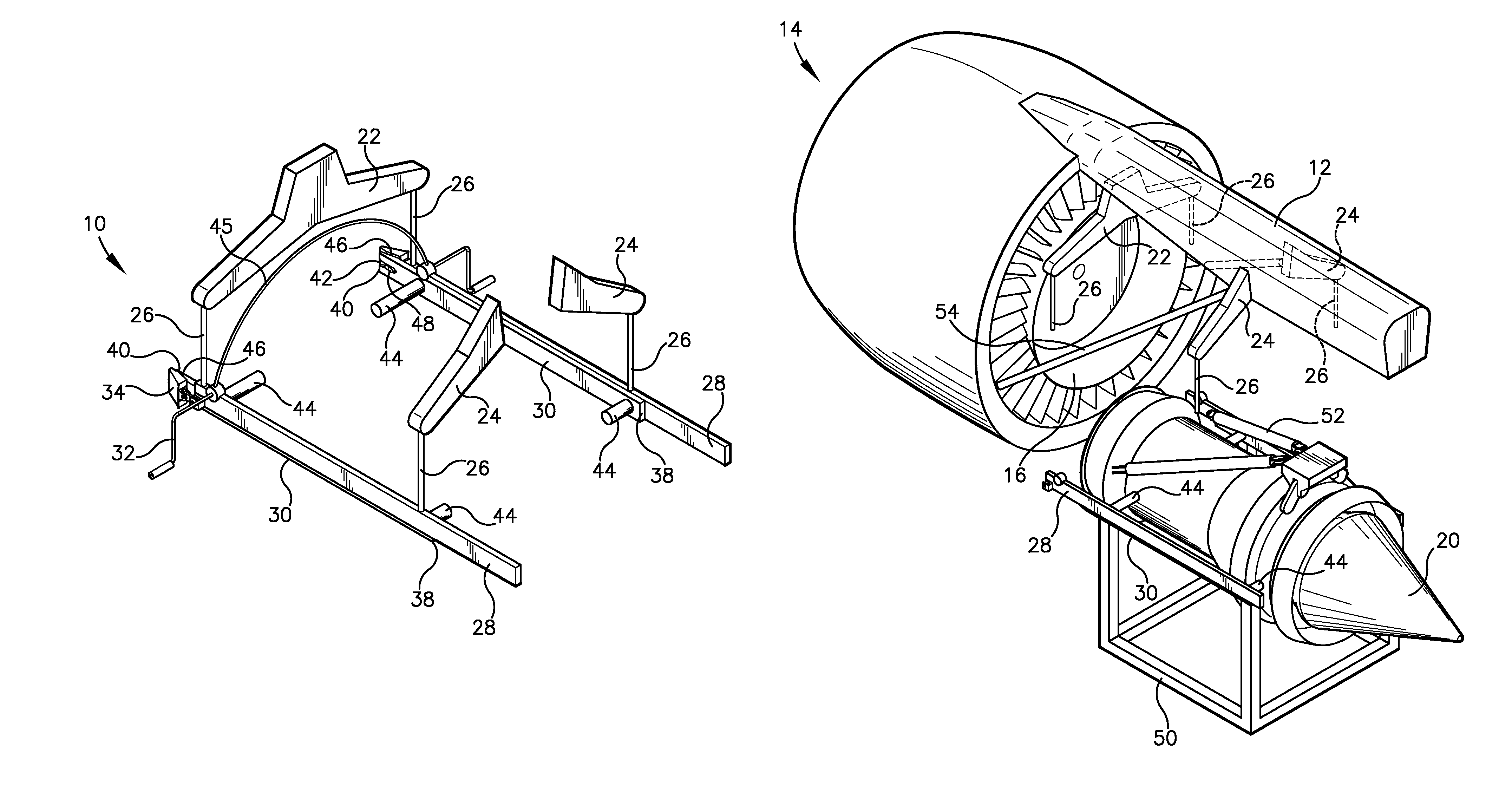
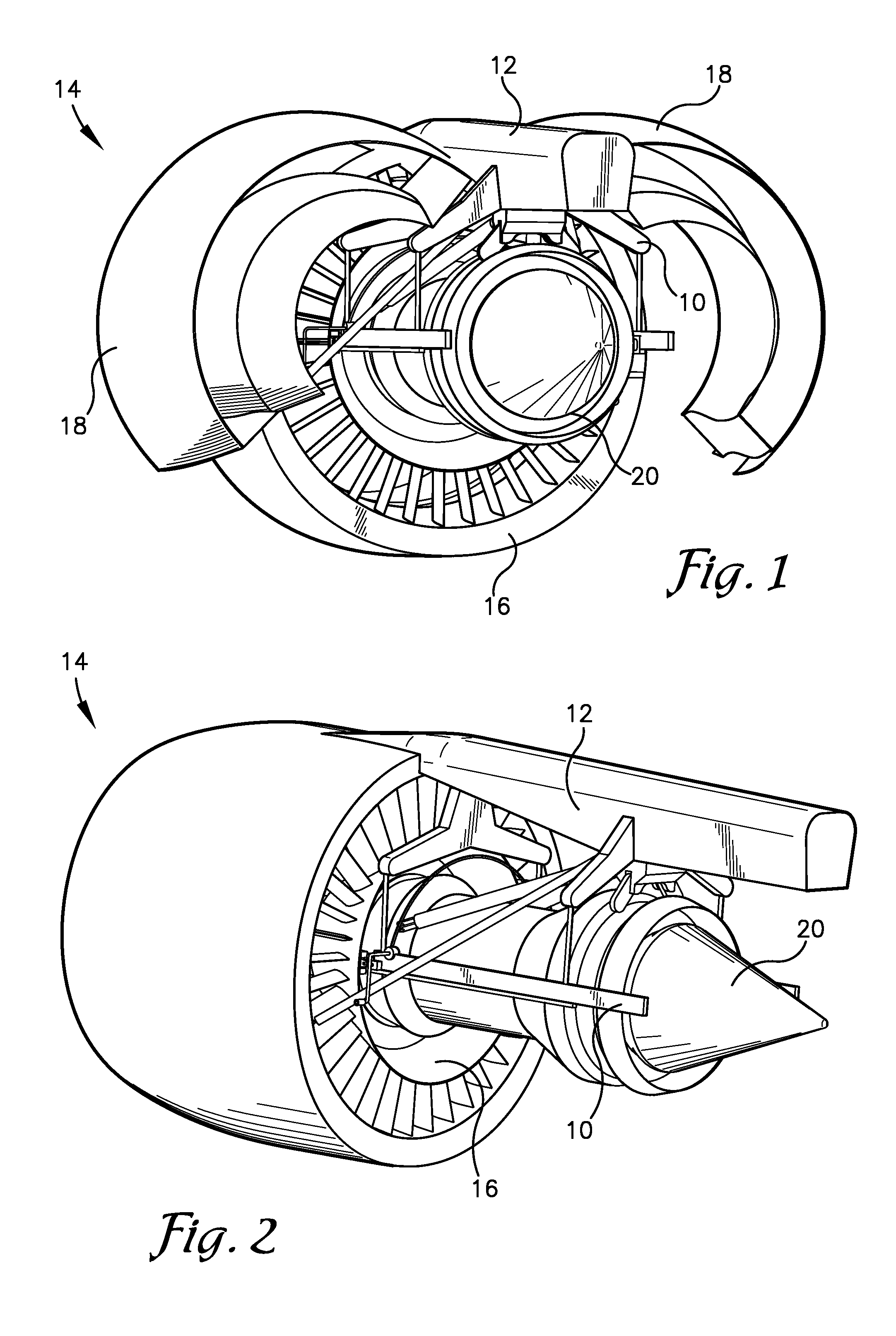
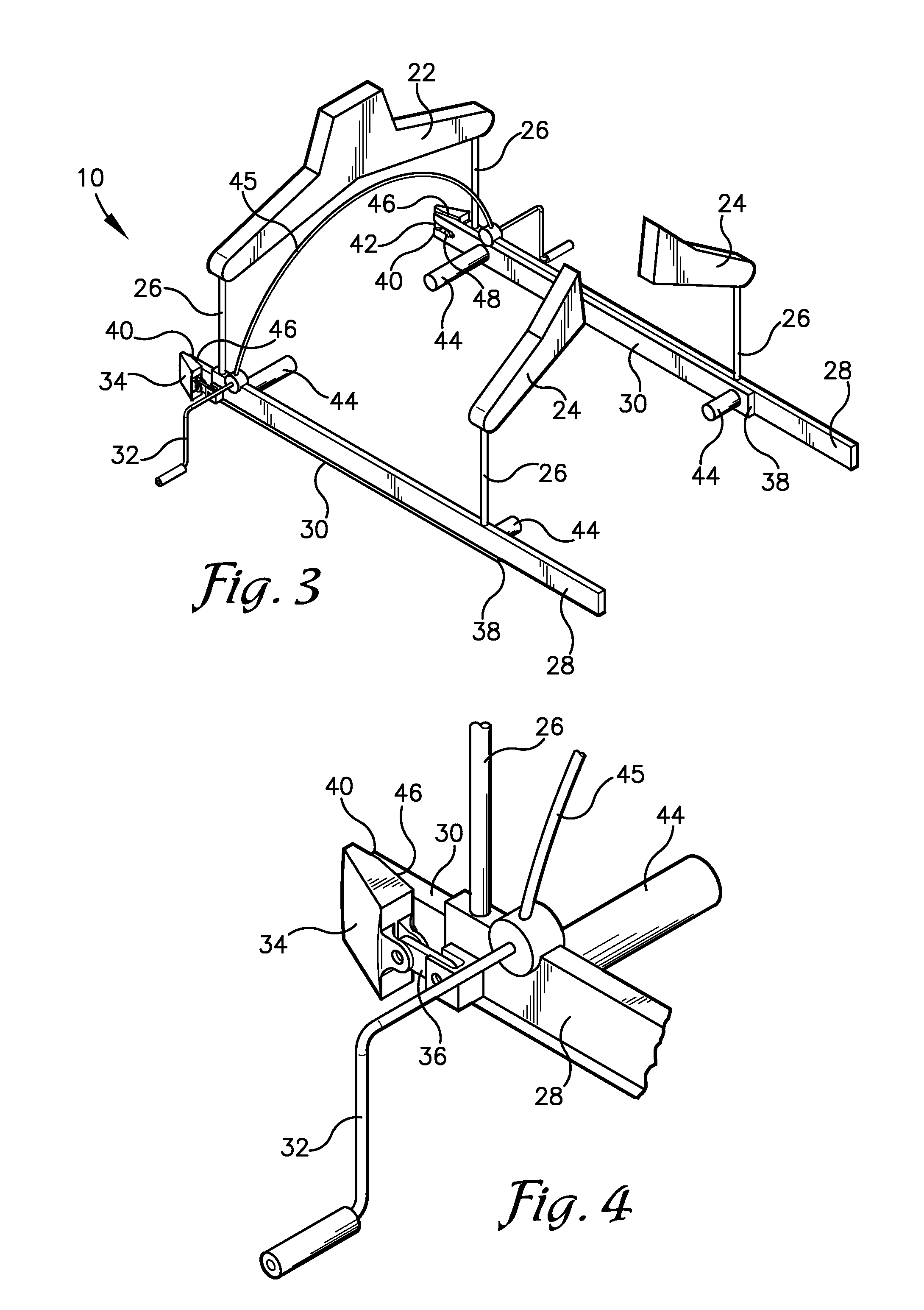
[0029]The following detailed description of the invention references the accompanying drawings that illustrate specific embodiments in which the invention can be practiced. The embodiments are intended to describe aspects of the invention in sufficient detail to enable those skilled in the art to practice the invention. Other embodiments can be utilized and changes can be made without departing from the scope of the present invention. The following detailed description is, therefore, not to be taken in a limiting sense. The scope of the present invention is defined only by the appended claims, along with the full scope of equivalents to which such claims are entitled.

[0030]In this description, references to “one embodiment”, “an embodiment”, or “embodiments” mean that the feature or features being referred to are included in at least one embodiment of the technology. Separate references to “one embodiment”, “an embodiment”, or “embodiments” in this description do not necessarily ref...


PUM

PropertyMeasurementUnit
timeaaaaaaaaaa
structureaaaaaaaaaa
strengthaaaaaaaaaa

Abstract

A method and ground support equipment (GSE) for attaching an engine core to an engine fan module on an aircraft pylon. The GSE may comprise GSE supports and lifting components attached to the pylon, two suspension rails attached to the lifting components, two translating rails translatably attached to the two suspensions rails and fixedly attached to opposite sides of the engine core, and two alignment fittings fixed to the engine fan module. The method of using the GSE may comprise lifting the engine core vertically using the lifting components and anchoring the suspension rails to the alignment fittings. The translating rails and engine core may then be translated in an aft-to-forward direction such that portions of the translating rails engage portions of the alignment fittings to cooperatively guide the translating rails into a final forward position in which the engine core is aligned relative to the engine fan module.

Description

BACKGROUND[0001]1. Field[0002]Embodiments of the present invention relate to methods and devices for mounting aircraft engine cores.[0003]2. Related Art[0004]Various aircraft engine core transport systems are used for mounting or removing an aircraft engine core into or out of a nacelle or engine fan module. However, these engine core transport systems are generally large and require removal of various nacelle components in order to insert or remove the engine core. This increases the amount of labor and time involved in exchanging an aircraft engine core. Furthermore, many prior art methods for installing engine cores do not accurately and efficiently align the engine cores with the engine fan modules.[0005]Accordingly, there is a need for an improved method and apparatus for mounting or removal of an aircraft engine core that overcomes the limitations of the prior art.SUMMARY[0006]This summary is provided to introduce a selection of concepts in a simplified form that are further d...

Claims


Application Information

Patent Timeline
Patent Type & Authority Patents(United States)
IPC IPC(8): B64F5/00F01D25/28
CPCF01D25/285B64F5/0036B64F5/50Y10T29/4932Y10T29/49329Y10T29/49327
Inventor WEST, RANDALL, RAY
Owner SPIRIT AEROSYSTEMS
Why Eureka
Try Eureka