Device for delivering conveying truck into screw driving area

a technology for conveying trucks and screw driving areas, which is applied in the direction of manufacturing tools, transportation and packaging, packaging, etc., can solve the problems of not being able to solve the problem of how, the practical delivery device of the conveying truck has not been proposed, and it is difficult to deliver the conveying truck in a timely manner. , to achieve the effect of avoiding large impact for

Active Publication Date: 2014-05-13
DAIFUKU CO LTD
View PDF10 Cites 3 Cited by
  • Summary
  • Abstract
  • Description
  • Claims
  • Application Information

AI Technical Summary

Benefits of technology

[0008]According to the configuration of the present invention, as described above, where a conveying truck is delivered to the screw driving area in the state of forward driving another conveying truck, the following conveying truck can be smoothly delivered at a necessary interval with respect to the preceding conveying truck driven forward at the screw driving area, if the single position electromagnetic clutch is switched into the engaged state at a necessary timing, as long as the conveying truck to be delivered is delivered by an appropriate means to a fixed position of the truck delivery screw in the freely rotatable state juxtaposed at the entrance of the screw driving area. That is, there is no need to temporarily stop the rotationally driven truck propulsion screw of the screw driving area or to deliver the conveying truck with precise timing with respect to the rotationally driven truck propulsion screw. The delivery of the conveying truck with respect to the screw driving area can be simply and easily performed without affecting at all the driving status of the preceding conveying truck within the screw driving area.
[0010]According to the foregoing configuration, a driven roller pull-in portion where the driven roller of the conveying truck can enter the spiral groove without interfering with the end portion of the screw main body constituting the truck delivery screw can be secured reliably at the entrance side end of the truck delivery screw having been switched into the freely rotatable state, regardless of timing of disengaging the electromagnetic clutch. Therefore, as described earlier, such labor can be eliminated as switching the electromagnetic clutch into the disengaged state at a fixed timing, or checking to see that the truck delivery screw is in the phase not interfering with the driven roller of the conveying truck each time when the conveying truck is delivered to the truck delivery screw side by the conveying truck delivery means, and having to rotate the truck delivery screw a necessary angle if there is the possibility of interference. As long as the truck delivery screw is in the freely rotatable state, the conveying truck can be delivered reliably to the fixed position of the truck delivery screw by the conveying truck delivery means.
[0012]According to this configuration, the held portion can be reliably held between the pair of front and back holding pieces and the conveying truck can be delivered to the fixed position of the truck delivery screw even if the position of the conveying truck whose delivery is started by the truck delivery means is slightly displaced forward or rearward, so long as the held portion of the conveying truck is located within an area corresponding to between the pair of opening and closing front and back holding pieces.
[0015]According to this configuration, the truck delivery screw not subjected to the turning force from the truck propulsion screw yet and in the freely rotatable state is forced to be rotated by the driven roller of the conveying truck through the second-stage delivery action of the truck delivery means having been started by an engaging of the electromagnetic clutch. After that, the truck delivery screw is subjected to the turning force from the truck propulsion screw via the electromagnetic clutch and then rotationally driven. That is, when the truck delivery screw is subjected to the turning force from the truck propulsion screw via the electromagnetic clutch and then rotationally driven, the truck delivery screw is already rotationally driven by the driven roller of the conveying truck forward traveling while subjected to the second-stage delivery action of the truck delivery means. Thus, a difference in rotational speed before and after the truck delivery screw is subjected to the turning force from the truck propulsion screw via the electromagnetic clutch can be made smaller depending on the setting of advancing speed of the conveying truck at the time of second-stage delivery action of the truck delivery means. As a result, a large impact force can be avoided from acting between the truck delivery screw and the driven roller of the conveying truck when the conveying truck is delivered to the screw driving area downstream thereof by the rotational drive of the truck delivery screw, and the delivery of the conveying truck can be reasonably and smoothly started even if the advancing speed of the conveying truck at the screw driving area is fast.

Problems solved by technology

At this moment, it is extremely difficult to deliver in a timely manner the conveying truck so as for the driven roller of the conveying truck to be smoothly entered into a spiral groove of the rotating truck propulsion screw located at an entrance of the screw driving area.
Practical conveying truck delivering devices have not been proposed yet.
However, no means for solving the problem of how to first deliver the conveying truck into the screw driving area described in Patent Document 1 is disclosed.

Method used


Image

  • Device for delivering conveying truck into screw driving area
  • Device for delivering conveying truck into screw driving area
  • Device for delivering conveying truck into screw driving area

Examples


Embodiment Construction

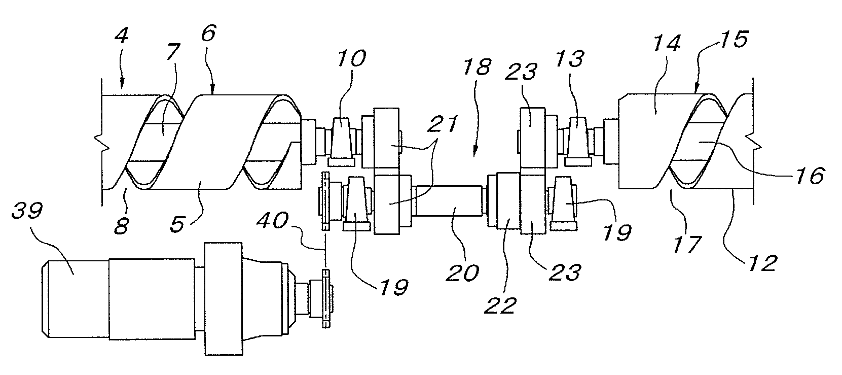
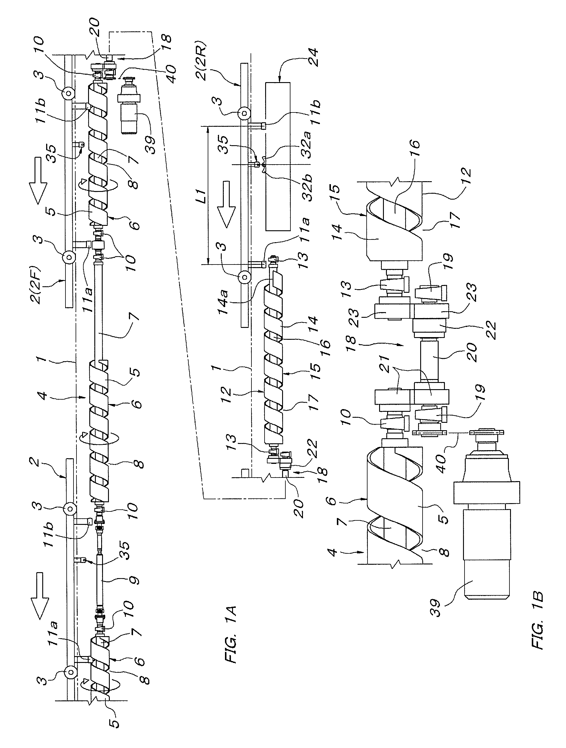
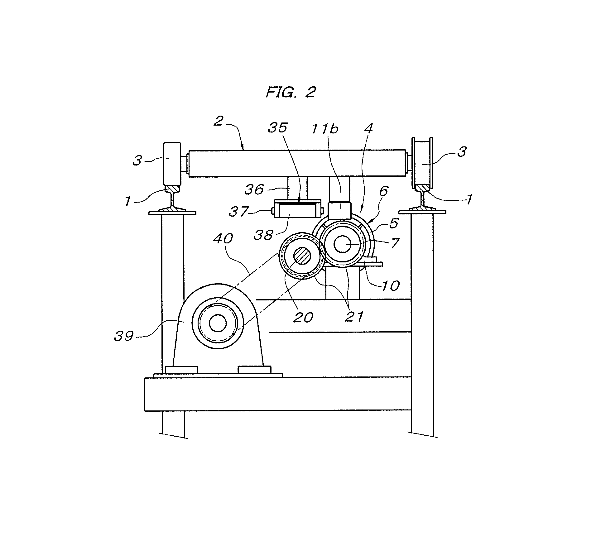
[0025]In FIGS. 1 to 4, reference numeral 1 denotes a pair of left and right guide rails constituting a truck travel path. A conveying truck 2 is supported to travel freely on these guide rails 1 via wheels 3. In the truck travel path, a screw driving area composed of a truck propulsion screw 4 supported in parallel with the truck travel path (the guide rails 1) below the truck travel path is provided. The foregoing truck propulsion screw 4 is constituted of a plurality of screw main bodies 6 in concentric series. Each screw main body 6 is formed by spirally winding a band plate 5 and is supported to a drive shaft 7 concentrically. A spiral groove portion 8 concentric with the drive shaft 7 is formed between adjacent band plates 5. The screw main bodies 6 have a fixed length and are arranged in concentric series at fixed intervals which are substantially equal to the length of the screw main bodies 6 and are an integral multiple of a feeding pitch of the spiral groove portion 8. Betw...


PUM


Abstract

A device for delivering a conveying truck into a screw driving area has a truck delivery screw and a truck propulsion screw which are connected in tandem via a single position electromagnetic clutch and both the screws are configured to rotate in the same phase in the transmission state of the electromagnetic clutch. Two front and back driven rollers are pivotally connected to a conveying truck at an interval at which the driven rollers can engage both screws. A truck delivery mechanism is provided for delivering the conveying truck in the disengaged state of the electromagnetic clutch while rotating the truck delivery screw by the front-side driven roller until the roller arrives at a fixed position in the truck delivery screw.

Description

FIELD OF THE INVENTION[0001]The present invention relates to a conveying truck delivering device for delivering a conveying truck into a screw driving area equipped with a truck propulsion screw to be engaged with a driven roller of the conveying truck and for starting screw drive.BACKGROUND OF THE INVENTION[0002]There is known screw-driven delivery equipment in which a rotationally driven truck propulsion screw is supported along a truck travel path at a screw driving area in the truck travel path and a driven roller to be engaged with the truck propulsion screw is supported to a conveying truck on the truck travel path. In screw-driven delivery equipment described in Japanese Unexamined Patent Application Publication No. 2010-47399, for example, it is known that the truck propulsion screw within the screw driving area is divided and front-rear adjacent truck propulsion screws are linked and coupled to each other via a single position electromagnetic clutch in which engagement is m...

Claims


Application Information

Patent Timeline
Patent Type & Authority Patents(United States)
IPC IPC(8): B65G33/32B65G33/04B65G33/34B65G33/02
CPCB65G33/04B61B13/125B65G35/066B65G33/34B21B41/00
Inventor IBA, TOSHIYUKI
Owner DAIFUKU CO LTD
Why Eureka
Try Eureka