System and method for cooling a densifier

a densifier and cooling system technology, applied in the field of densifiers, can solve the problems of many plastics taking a very long time to biodegrade, eps, and certain types of lightweight plastics, and achieve the effects of increasing the volume output, increasing the density of the output log or bale, and increasing the speed of the screw

Active Publication Date: 2014-05-13
KOMAR IND LLC
View PDF58 Cites 3 Cited by
  • Summary
  • Abstract
  • Description
  • Claims
  • Application Information

AI Technical Summary

Benefits of technology

[0011]Exemplary embodiments of the cooling system and method may also provide increased volume output of the compression screw through increased speed of the screw, which is facilitated by temperature control of at least the distal end and / or at least one compression flight of the screw.
[0012]Further, exemplary embodiments of the cooling system and method may provide increased density of the output log or bale through additional force applied to the screw, which is facilitated by temperature control of at least the distal end and / or at least one compression flight of the screw.
[0013]Exemplary embodiments of the cooling system and method may also provide a novel combination in which a baffling apparatus is provided in the bore of the shaft and / or at least one flight, whereby circulation of temperature controlled fluids may take place in the desired bore and / or formed flight pockets.

Problems solved by technology

Additionally, certain types of lightweight plastics, such as, for example, expanded polystyrene (EPS), extruded polystyrene foam, and expanded polypropylene foam are not easily recycled because of their light weight and low scrap value.
Many plastics take a very long period of time to biodegrade, if they biodegrade.
Furthermore, certain types of lightweight plastics may not only float on water, but may also blow in the wind, causing an abundant amount of litter, especially along shores and waterways.
The known screw densifiers and related methods are less than ideal for densifying or compacting materials.
One of the main problems that occur during the densifying process is that the mechanical components used to contact the plastic throughout the screw densification process may heat to undesired levels.
Densifiers that use screw compaction have an especially inherent problem with material melt or plasticizing of the material due to the high heat.
This occurs when the coefficient of friction between the material and typically the end surface of the compression screw generates high temperatures.
Thus, plastics and other materials that have low melt points may be particularly vulnerable to melting during operation of known densifiers.
For example, the unwanted temperature of the compression screw may be around 300 degrees Fahrenheit, which may be when the plasticizing of the material occurs.
With many materials, it is highly undesirable for the materials to melt during the densification process because the melting may change the composition and / or properties of the material.
For example, melting the material may change its functional properties, which may limit its future uses and hence reduce its value.
Also, melting the material may change the characteristics of the output (e.g., the density or size of the log) of the densification process, which may reduce the quality of the output and / or impair the operation of the densifier.
Ceasing the continuous operation of the densifier may add extra time and cost to the recycling process.

Method used


Image

  • System and method for cooling a densifier
  • System and method for cooling a densifier
  • System and method for cooling a densifier

Examples


Embodiment Construction

)

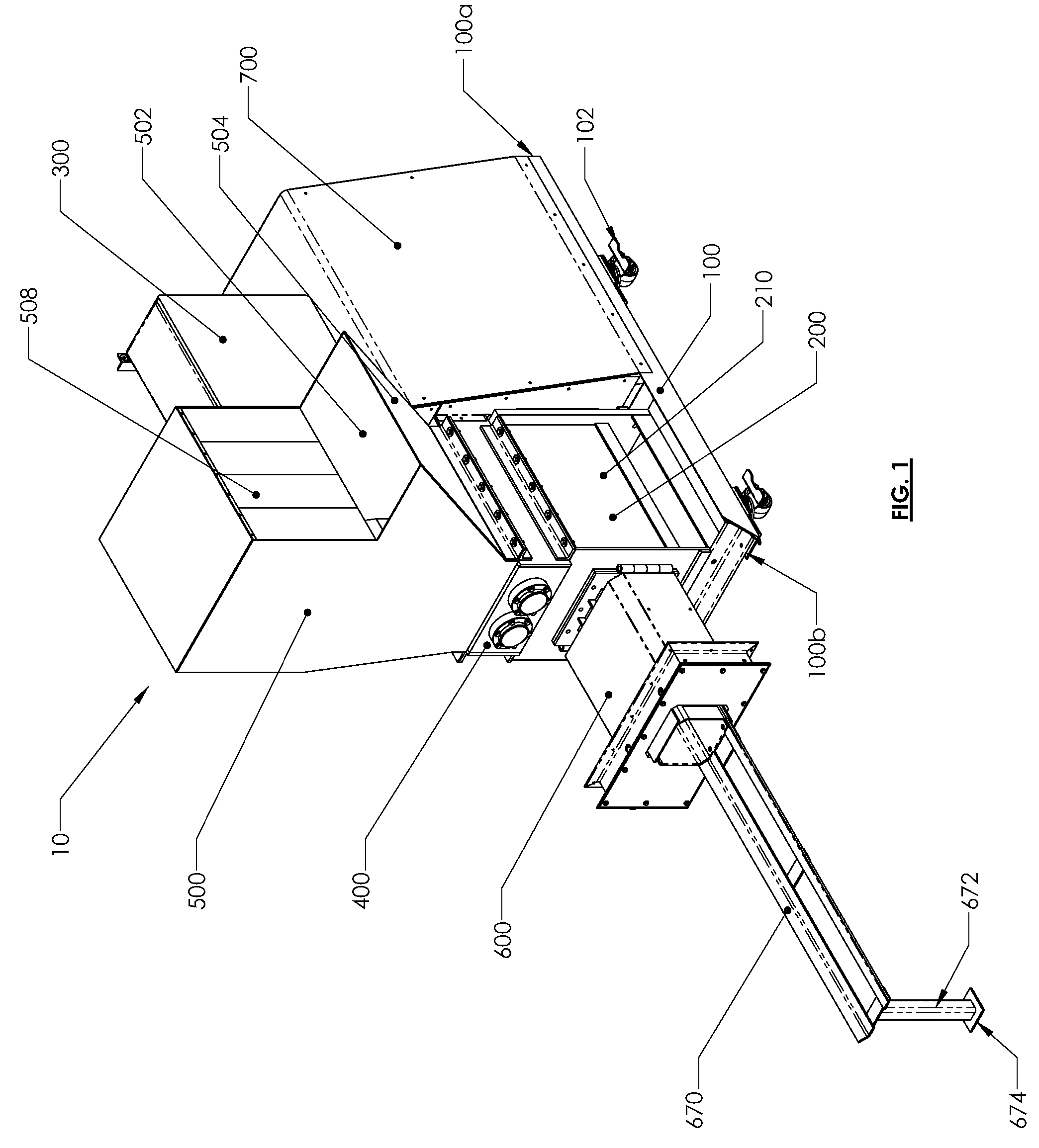
[0080]As seen in FIG. 1, exemplary embodiments of a densifier 10 that may be adapted to densify plastics or other materials are illustrated. Exemplary embodiments may include a frame 100 with a proximal end 100a and a distal end 100b such that rolling wheels 102 are attached to the frame 100. In other exemplary embodiments, the frame 100 may be adapted to mount or sit on different surfaces without the inclusion of wheels.

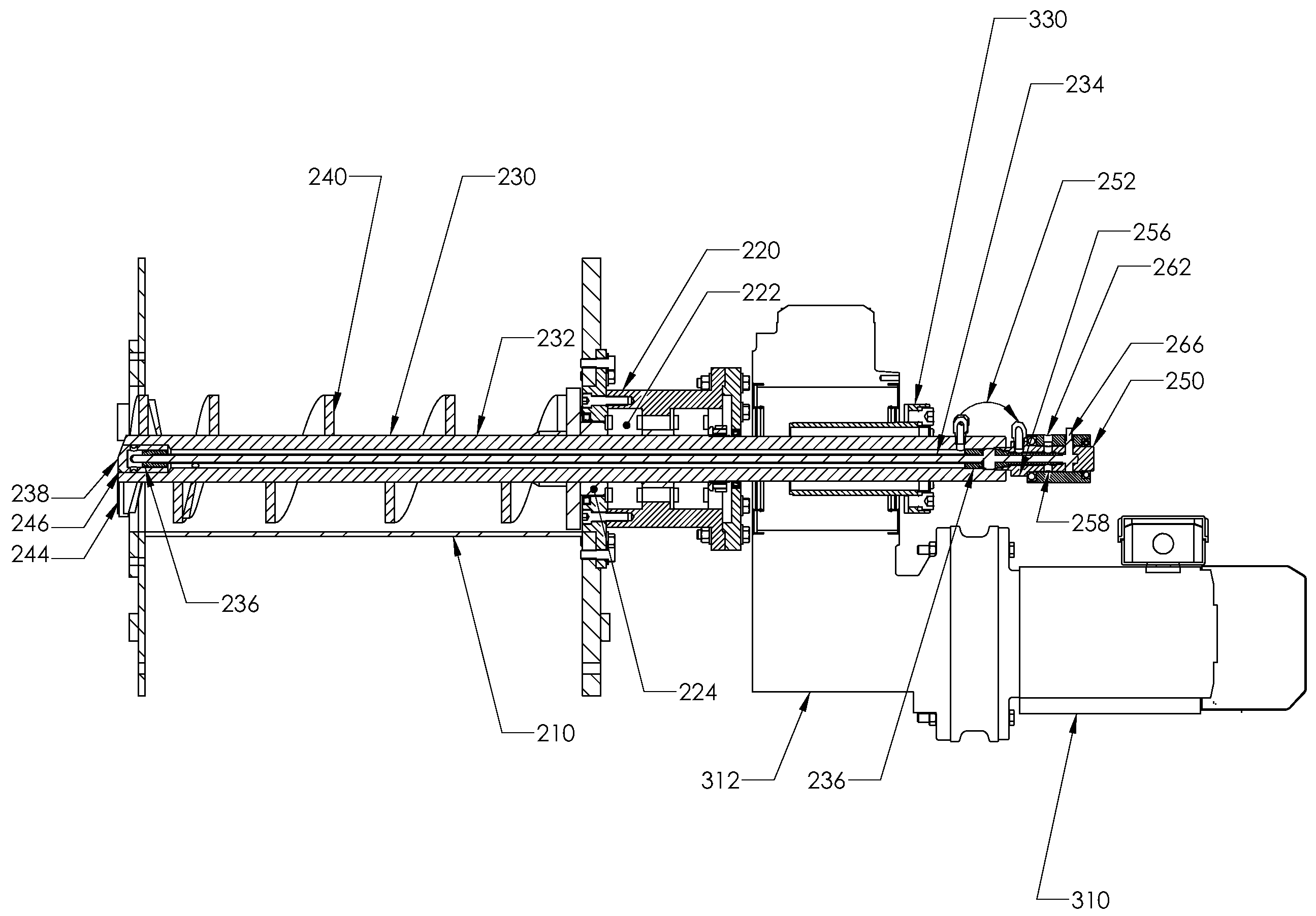
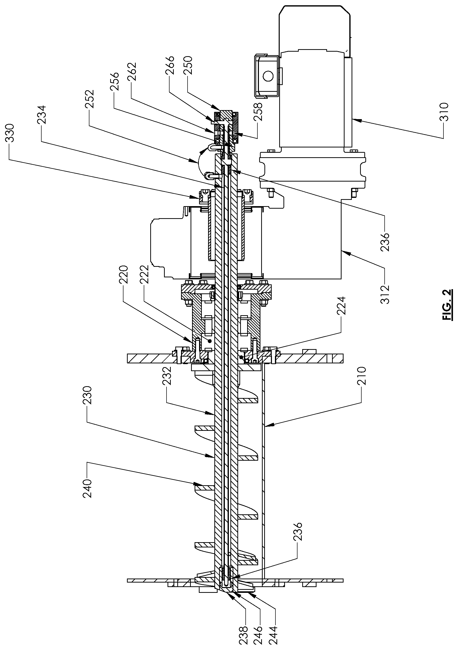
[0081]Exemplary embodiments of the densifier 10 may include a compactor module 200 that is mounted to the frame 100, as seen in FIGS. 2 and 3A. The compactor module 200 includes a grinding chamber 210 that surrounds a compression screw 230 and other components. The walls of the grinding chamber 210 may be fabricated from materials that are strong enough to withstand the force exerted by the materials that are densified by the compression screw 230 during use of the densifier 10. One example of the grinding chamber 210 may be cuboid in geometry, with at least one op...


PUM


Abstract

Exemplary embodiments relate to a system for cooling a compression screw that includes a compression screw. The system may include a hollowed shaft, a tubular body extending through a proximal end portion to a distal end portion of the hollowed shaft, at least one flight, including a chamber in fluid connection with the tubular body, and a rotary union connected with the compression screw shaft, which is adapted to allow fluid to flow from a relatively stationary inlet into the compression screw such that fluid is adapted to be circulated through the tubular body and the at least one flight for cooling the compression screw.

Description

CROSS-REFERENCE TO RELATED APPLICATIONS[0001]This application claims the benefit of U.S. Provisional Application No. 61 / 229,527, filed Jul. 29, 2009, which is hereby incorporated by reference as if fully recited herein.BACKGROUND AND SUMMARY OF THE INVENTION[0002]Exemplary embodiments of the invention are related to a densifier. More particularly, exemplary embodiments include a densifier that has a system that facilitates cooling of mechanical components of the densifier to promote relatively prolonged or continuous use of the densifier. Exemplary embodiments of the invention also include a related method for cooling a densifier. A further exemplary embodiment relates to a system and method for adjusting a densifier such as to improve the output and / or to clean the densifier.[0003]The amount of materials ending up in landfills is continuously increasing. As the scarcity of landfill space increases, along with more stringent environmental regulations, there have been increased effor...

Claims


Application Information

Patent Timeline
Patent Type & Authority Patents(United States)
IPC IPC(8): B02C19/22
CPCB30B9/3082B30B9/18B30B11/246B30B15/34
Inventor KOENIG, LARRY, E.
Owner KOMAR IND LLC
Why Eureka
Try Eureka