Clamping device for holding and clamping components

a technology for clamping components and clamping devices, which is applied in the direction of metal-working feeding devices, auxillary welding devices, soldering devices, etc., can solve the problems that the clamping device generally hampers the access to components, and achieve the effect of avoiding the disruption of contours

Active Publication Date: 2014-05-13
FFT PRODIONSSYST
View PDF12 Cites 74 Cited by
  • Summary
  • Abstract
  • Description
  • Claims
  • Application Information

AI Technical Summary

Benefits of technology

[0006]It is an objective of the invention to avoid that disruptive contours are created by clamping components to be joined.
[0009]The clamping structure may be of an arching type shape or at least form an arch, and the arch or several arches extends or extend around the peripheral edge of the component holders. In particular, it may have a shape in the form of a double arch, i.e. a frame which extends round the component holders on two sides of the peripheral edge. The arch or arches or the frame preferably forms or form an at least partially two-dimensional pattern so that, in the case of a multiple arch, for example in the case of the preferred frame, the several arches or the frame extend or extends around the component holders at opposing sides of the peripheral edge facing away from one another. A frame is preferable to a single arch due to its higher mechanical strength. A single arch, on the other hand, forms fewer disruptive contours.
[0010]Since the clamping structure extends round the peripheral edge of the component holders, preferably at a distance from them, the peripheral edge is accessible everywhere, at least in principle. In order to improve accessibility still further, the component holders secured relative to one another in the joining position and the clamping structure can be moved relative to one another, and the ability to move is such that the position of at least a clamping structure region extending round the peripheral edge or preferably the position of the clamping structure as a whole can be varied in the longitudinal direction of the peripheral edge due to the relative movement. In preferred embodiments, the clamping structure is displaceably connected to the component holders in such a way that a joining tool can be moved from a start position in a revolution extending in space about an axis over 360°, preferably in an intrinsically closed circuit, around the region of the component holders where the clamping structure is supported in order to transmit the clamping force during the joining process. During the revolution, the clamping structure is able to run ahead or back by at least a distance in the same direction so that the joining tool can be moved from the clamping structure back into the start position unhindered. However, it is also of advantage to use a clamping structure extending round the peripheral edge where the path along which the components have to be joined is not closed. The relative displaceability is also of advantage in these situations in order to avoid obstructing the joining tool.
[0019]In the case of the design based on clamping device parts with coupling halves, which are complete in the sense that they establish the coupled engagement through pure contact, which should be such that they can be blocked in order to secure as well as facilitate the release of the coupled engagement, the clamping device is best suited for use in mass production facilities with short cycle times. To this end, the coupling halves are advantageously shaped and disposed on the relevant clamping device part so that the coupled engagement can be established by a simple movement of one clamping device part relative to the other, preferably by means of a short-stroke linear movement. In the preferred embodiments, it is sufficient simply to establish the coupled engagement in order to clamp the component holders and hence the held components relative to one another in the joining position. If, for example, the first component holder is attached to an actuator which can be freely moved in space, preferably a robot arm, a first component can be held by the first component holder by positioning the first component holder relative to the relevant first component and picking up and holding the first component in order to pick up the second component holder and hence with it also the second component by means of the first component holder, namely by simply establishing the coupled engagement. It is also of particular advantage that the second component holder not only serves as a means for supporting a second component but can also be used in another function as a removal device on completion of the joining process in that the first component holder releases the first component and hence the joined unit obtained from the components at the end of the joining process. Having been released, the joined unit can then be removed from the second component holder. The first component holder is already free again and is ready to hold the next first component, for example.

Problems solved by technology

The clamping device generally hampers accessibility to the components which are to be mutually joined and constitutes a disruptive contour for the joining unit performing the joining process.
During hemming, which is the preferred application of the invention, this causes problems, especially when hemming along a path along an outer peripheral edge of the components to be joined to one another which runs back on itself.

Method used


Image

  • Clamping device for holding and clamping components
  • Clamping device for holding and clamping components
  • Clamping device for holding and clamping components

Examples


Embodiment Construction

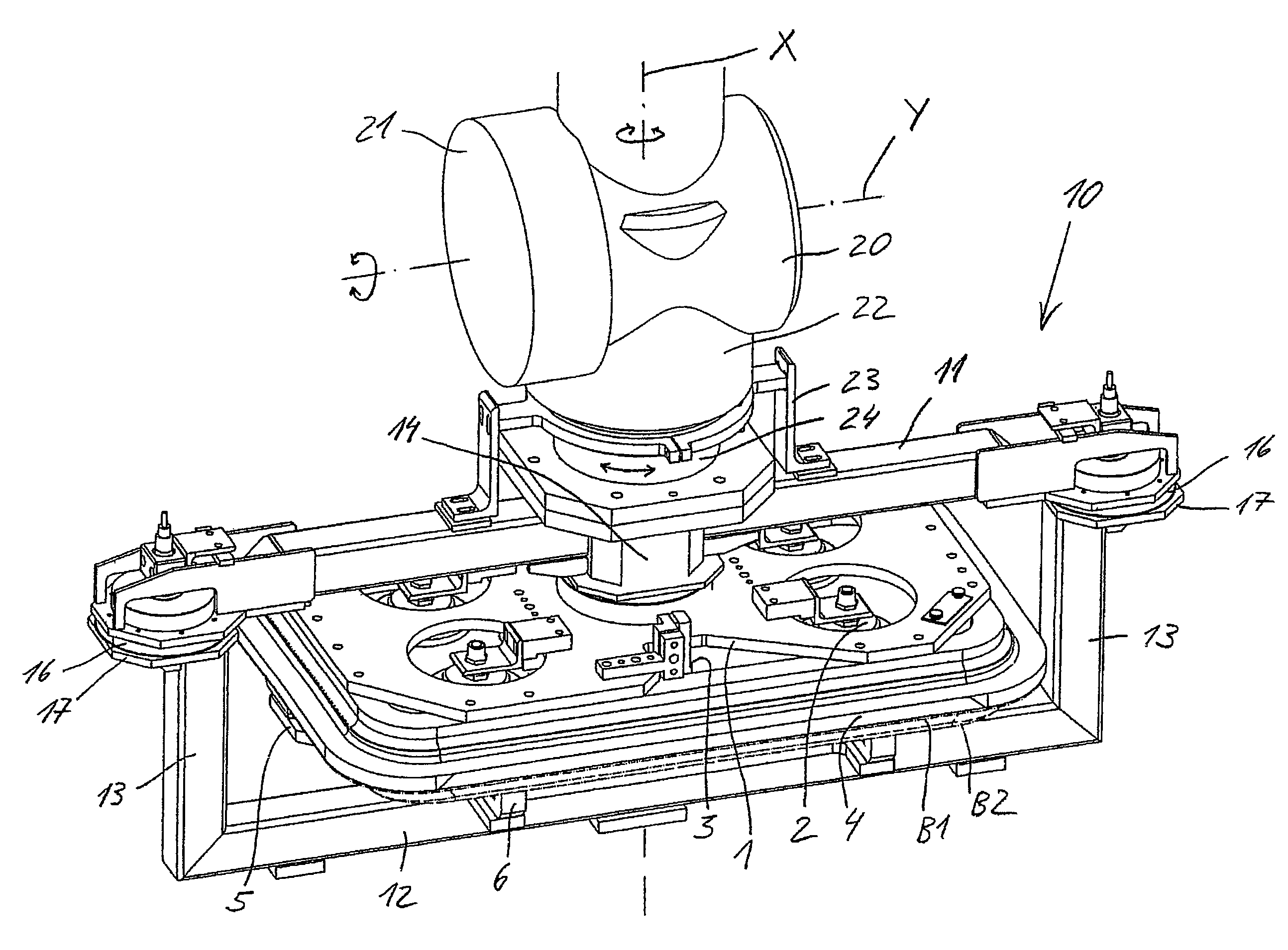
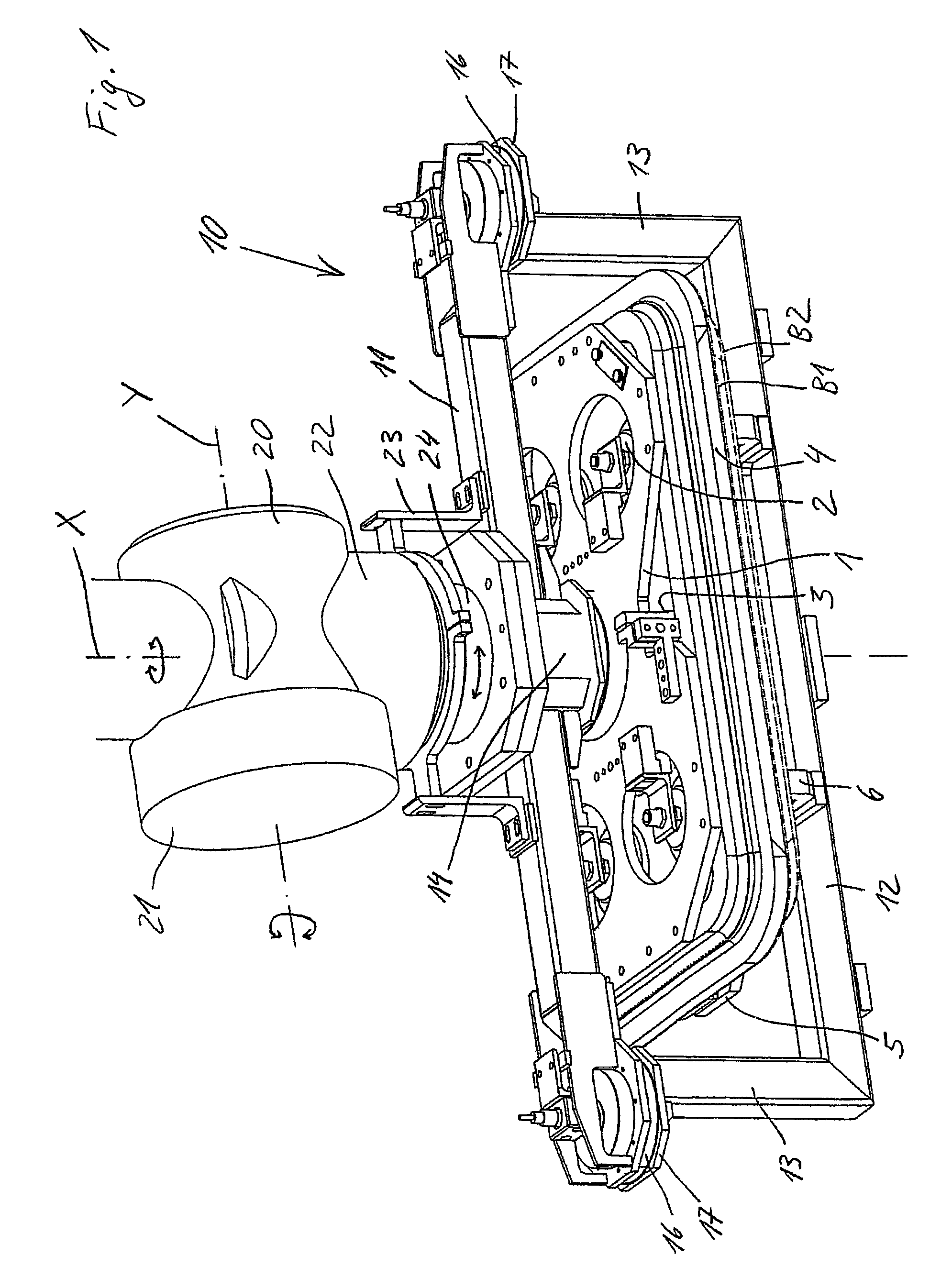
[0035]FIG. 1 illustrates a clamping device of the type used by preference for a flying joining process, in particular roller hemming, based on an example of a first embodiment. The clamping device is used to clamp two components B1 and B2 to be fixedly joined to one another along their outer peripheral edge to form a joined unit after the joining process. The clamping device clamps the components B1 and B2 relative to one another in a joining position which they also assume after the joining process. In the clamped state, the components B1 and B2 are joined along their outer peripheral edge, preferably by roller hemming. A single joining tool effects a complete revolution in order to produce the join. Alternatively, several tools may be distributed along the outer peripheral edge, each of which joins only a part-portion of the peripheral edge. During the preferred joining process based on roller hemming, several tool heads with hemming rollers set at differing angles of inclination ...


PUM

PropertyMeasurementUnit
electric poweraaaaaaaaaa
degree of freedomaaaaaaaaaa
thicknessaaaaaaaaaa

Abstract

A clamping device for components to be joined, which clamping device comprises: a first component holder for a first component, a second component holder for a second component, and a clamping structure which secures the component holders relative to one another in a joining position, and when the component holders are in the joining position, the clamping structure extends from an external face of the first component holder to an external face of the second component holder facing away from the external face of the first component holder and extends respectively around a peripheral edge of the component holders.

Description

[0001]This application is the U.S. national phase application of PCT International Application No. PCT / EP2007 / 0027457, filed Mar. 28, 2007, which claims priority to German Patent Application No. DE102006014279.9, filed Mar. 28, 2006, the contents of such applications being incorporated by reference herein in their entirety.BACKGROUND OF THE INVENTION[0002]1. Field of the Invention[0003]The invention relates to a device for clamping components to be joined to one another, a clamping device part as such, a joining device with a joining tool for joining the components, preferably by hemming, as well as a joining method. The invention may be used in particular for roller hemming sheet metal structures, preferably in the automotive industry. One particularly preferred application is that of mass-producing chassis or chassis parts, in particular attaching parts, of automotive vehicles.[0004]2. Description of the Related Art[0005]In order to join components, the components are clamped rela...

Claims


Application Information

Patent Timeline
Patent Type & Authority Patents(United States)
IPC IPC(8): B23Q1/64
CPCB23K37/0452B21D43/105B23P19/00B21D39/021B25J15/00B23K37/0443Y10T29/49998B21D39/02B21J15/42B25B5/14
Inventor REITH, STEFANKOERBEL, CHRISTIAN
Owner FFT PRODIONSSYST
Why Eureka
Try Eureka