
Ski with a connecting device for a ski binding
a connecting device and ski binding technology, applied in the direction of ski bindings, skiing, sport apparatus, etc., can solve the problems of limited maximum travel distance between these components and the limitation of the free extension of the flexural element so as to and reduce the interference of the connecting device.
- Summary
- Abstract
- Description
- Claims
- Application Information
AI Technical Summary
Benefits of technology
Problems solved by technology
Method used
Image

Examples
Embodiment Construction
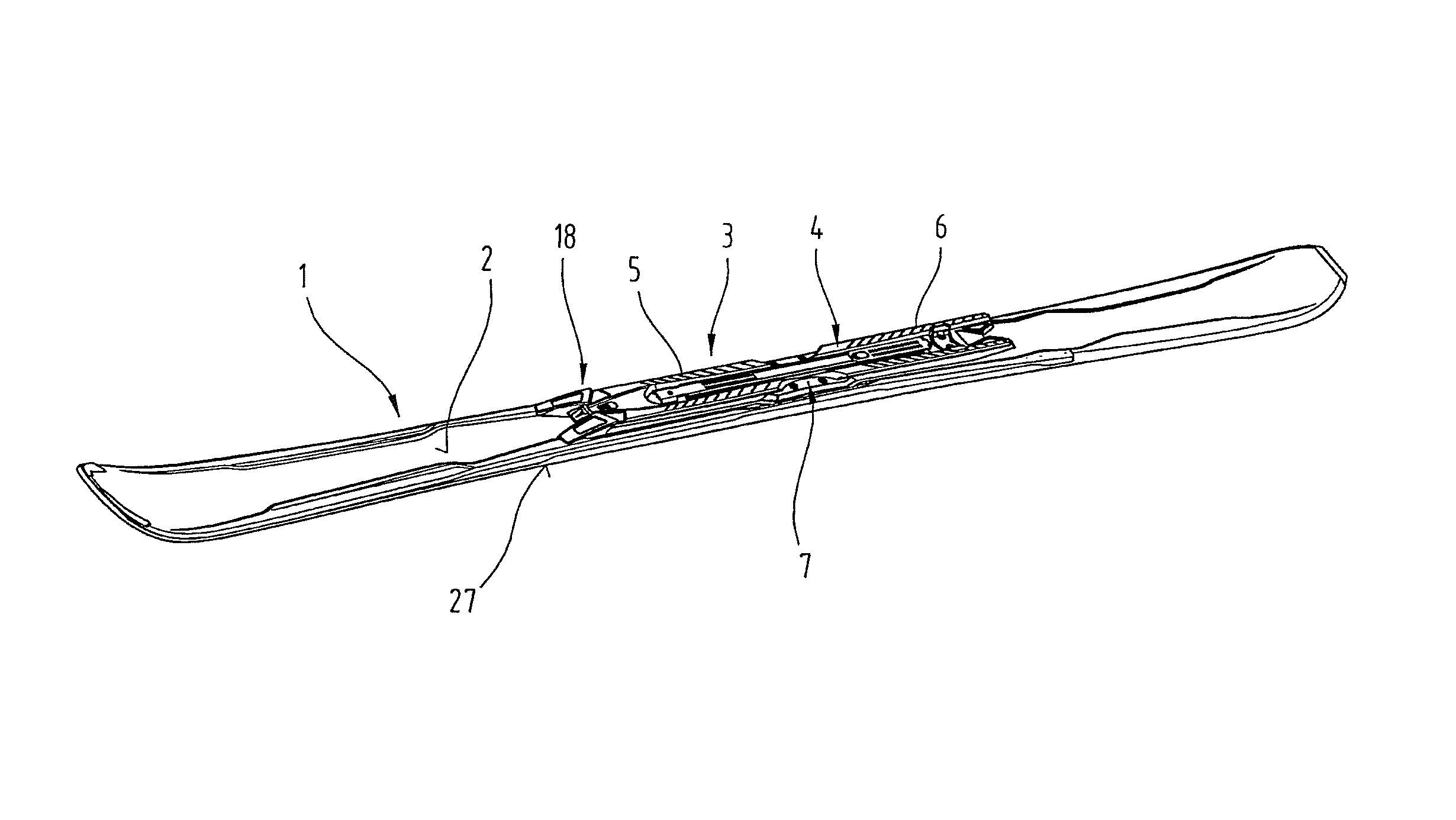
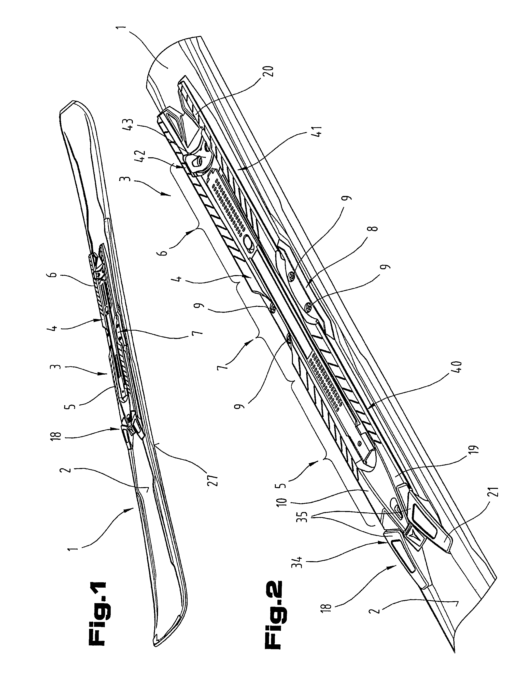
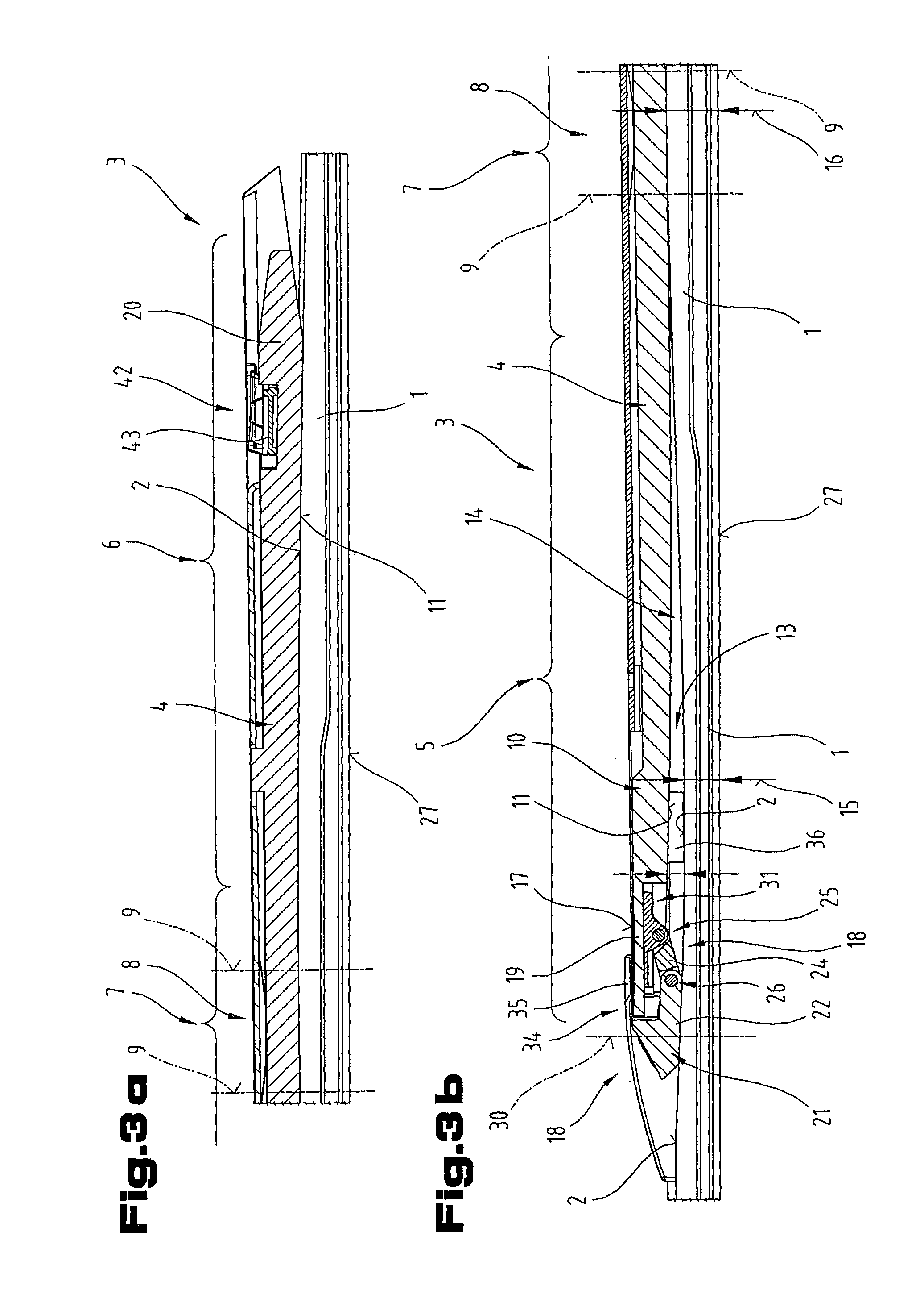
[0029]Firstly, it should be pointed out that the same parts described in the different embodiments are denoted by the same reference numbers and the same component names and the disclosures made throughout the description can be transposed in terms of meaning to same parts bearing the same reference numbers or same component names. Furthermore, the positions chosen for the purposes of the description, such as top, bottom, side, etc., relate to the drawing specifically being described and can be transposed in terms of meaning to a new position when another position is being described. Individual features or combinations of features from the different embodiments illustrated and described may be construed as independent inventive solutions or solutions proposed by the invention in their own right.
[0030]All the figures relating to ranges of values in the description should be construed as meaning that they include any and all part-ranges, in which case, for example, the range of 1 to 1...
PUM
 Abstract
Description
Claims
Application Information