High transmission optoelectonic mechanical assembly

a technology of optoelectonic and mechanical assembly, applied in the field of optogenetics, can solve the problems of cord torsion and affect the beam quality in a way which was unsatisfactory for at least some optogenetic applications, and achieve the effect of low resistance to rotation of the optic fiber patch cord, high image or beam, and low resistance to rotation

Active Publication Date: 2014-05-13
LES LENTILLES DORIC INC DORIC LENSE
View PDF7 Cites 2 Cited by
  • Summary
  • Abstract
  • Description
  • Claims
  • Application Information

AI Technical Summary

Benefits of technology

[0005]This specification describes a rotary joint which has a light source embedded therein, and by which an optic fiber patch cord can be directly, and rotatably coupled to the light source. The rotary joint with integrated light source allows achieving a very high image, or beam, quality and allows a very low resistance to rotation of the optic fiber patch cord, thereby making it particularly suitable to optogenetic applications on laboratory mice especially since the torsion resistance of the optical fiber implanted in the head of the mice is limited.

Problems solved by technology

As the mouse moves about in its cage, it can subject the fiber-optic patch cord to torsion which is both uncomfortable for the mice and can subject the fiber-optic patch cord to torsion, which is undesired.
However, this led to two optical connections in the patch cord, a first one between the light source and the first section, and a second one across the rotary joint, which affected the beam quality in a way which was unsatisfactory for at least some optogenetic applications.

Method used


Image

  • High transmission optoelectonic mechanical assembly
  • High transmission optoelectonic mechanical assembly
  • High transmission optoelectonic mechanical assembly

Examples


Embodiment Construction

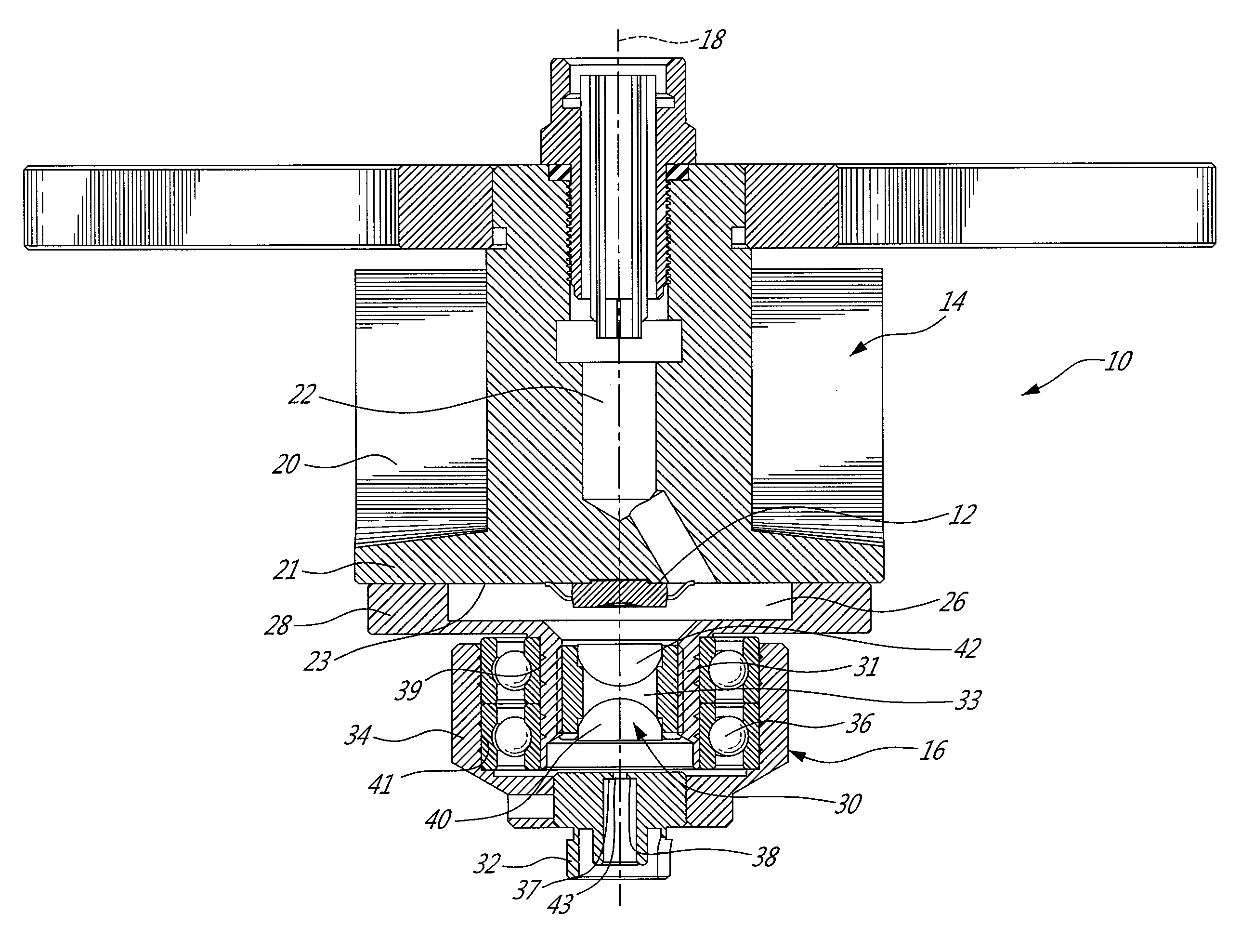
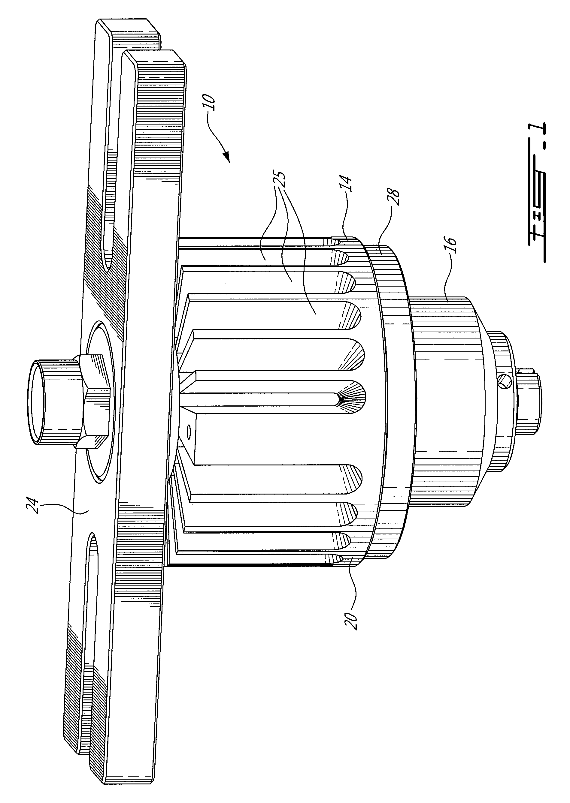
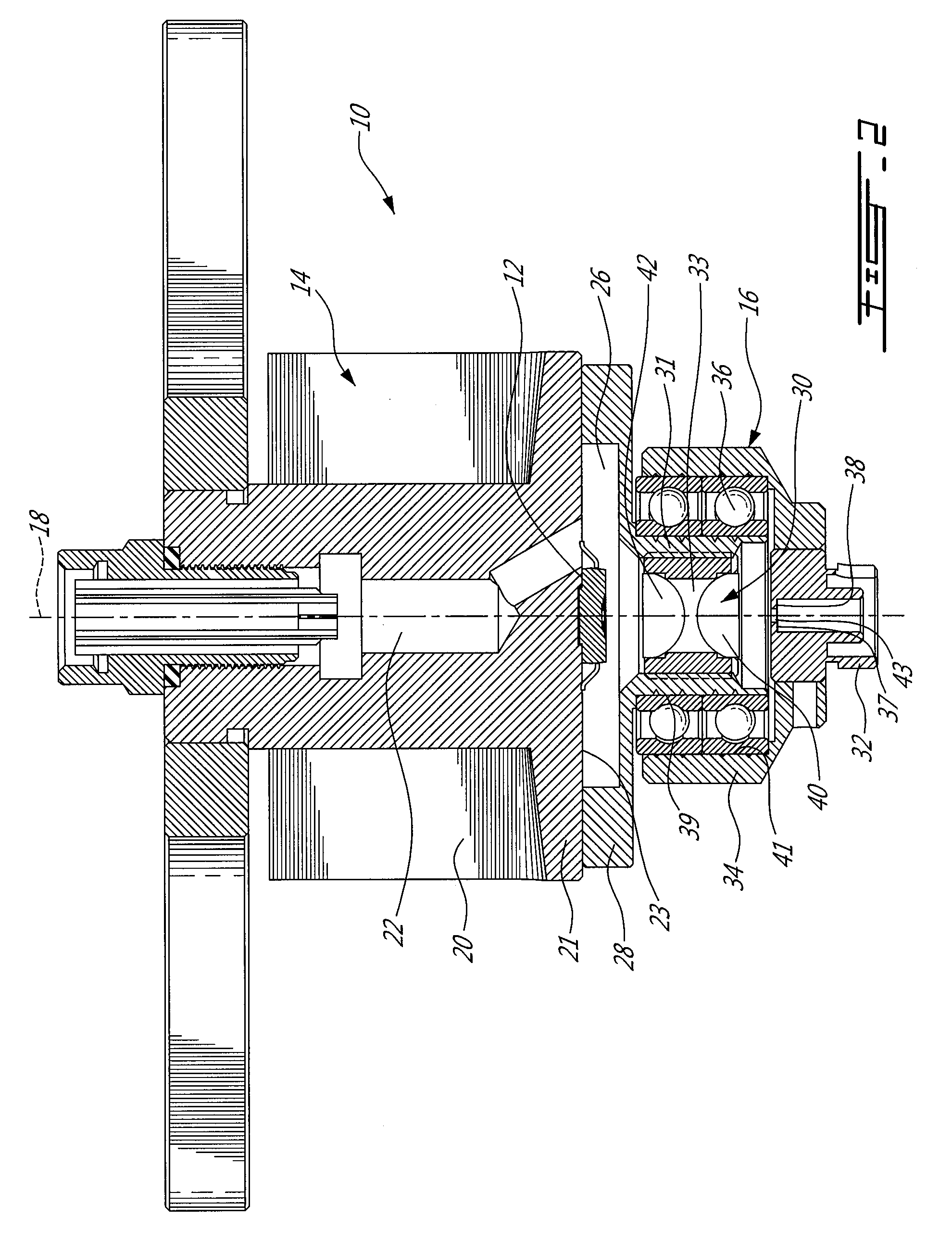
[0016]FIGS. 1 and 2 generally show an example of an optoelectronic mechanical assembly 10 having an integrated light source 12. More specifically, the assembly 10 can be seen to generally have a fixable structure 14, and a rotary structure 16 rotatably mounted to the fixable structure 14 so as to rotate about an optical rotation axis 18.

[0017]The fixable structure 14 generally includes a light source 12, which can be a LED or laser diode arrangement for instance (multiple source arrangements are possible as well as presented below), which is mounted to a heat sink 20 in order to evacuate heat therefrom during operation. In this particular embodiment, the heat sink 20 is a passive heat sink that addresses potential overheating of the light source 12. Overheating of the light source 12 is typically undesired and has been known to reduce the optical power of LEDs and / or decrease the expected lifespan thereof. The heat sink has a hub 21 having a flat surface 23 receiving the light sourc...


PUM


Abstract

The optoelectronic mechanical assembly can have an integrated light source and couple a non-rotary light outlet thereof directly into a tip of a freely rotatable optical fiber. The assembly includes a fixable structure which can house a light source, and a rotary structure which receives the optical fiber and which is mounted to the fixable structure by way of at least one bearing, in a manner to maintain the optical alignment of the optical fiber with the non-rotary outlet. If more than one light source is used, they can be combined into the common outlet by a beam combiner.

Description

CROSS-REFERENCE TO RELATED APPLICATIONS[0001]This application claims priority to U.S. provisional application 61 / 579,696, filed Dec. 23, 2011, and to U.S. provisional application 61 / 678,822, filed Aug. 2, 2012, both of which are hereby incorporated by reference.FIELD[0002]This specification relates to the field of optogenetics, and more specifically pertains to a rotary joint for coupling a non-rotary light outlet into a tip of a freely rotatable optical fiber.BACKGROUND[0003]Many optogenetic applications involve injecting light into a living organism. Many experiments are done on laboratory mice worldwide to develop this promising field of health sciences. In this context, the mouse has an implant on its head to inject the light into their brain cells, and typically keeps this implant until the end of its life. The implant has one end of a fiber-optic patch cord (or cable), the other end of which is connected to a light source.[0004]As the mouse moves about in its cage, it can subj...

Claims


Application Information

Patent Timeline
Patent Type & Authority Patents(United States)
IPC IPC(8): G02B6/36
CPCG02B6/4269G02B6/3604G02B6/4298G02B6/4204
Inventor DORIC, SEAD
Owner LES LENTILLES DORIC INC DORIC LENSE
Why Eureka
Try Eureka