Light guiding device

a technology of light guide and light tube, which is applied in the direction of photometry, solar radiation concentration, sustainable buildings, etc., can solve the problems of heliostat systems that are usually very elaborate, large, and expensive, and achieve the effect of reducing the cost of heliostats, reducing and improving the efficiency of light tubes

Inactive Publication Date: 2014-05-13
BARTENBACH HLDG
View PDF14 Cites 9 Cited by
  • Summary
  • Abstract
  • Description
  • Claims
  • Application Information

AI Technical Summary

Benefits of technology

[0027]In order to capture a maximum amount of sunlight even if the position of the sun is low an arrangement of the blades might be of advantage wherein the blades which are located towards the rear will be arranged in a higher position than those which are located towards the front. For this the blade holder may be provided in a position wherein it may be tilted parallel to the swivel axes of the blades abo...

Problems solved by technology

However, efficiency of such light tubes depends on the position of the sun and will be especially compromised dur...

Method used


Image

  • Light guiding device
  • Light guiding device
  • Light guiding device

Examples


Embodiment Construction

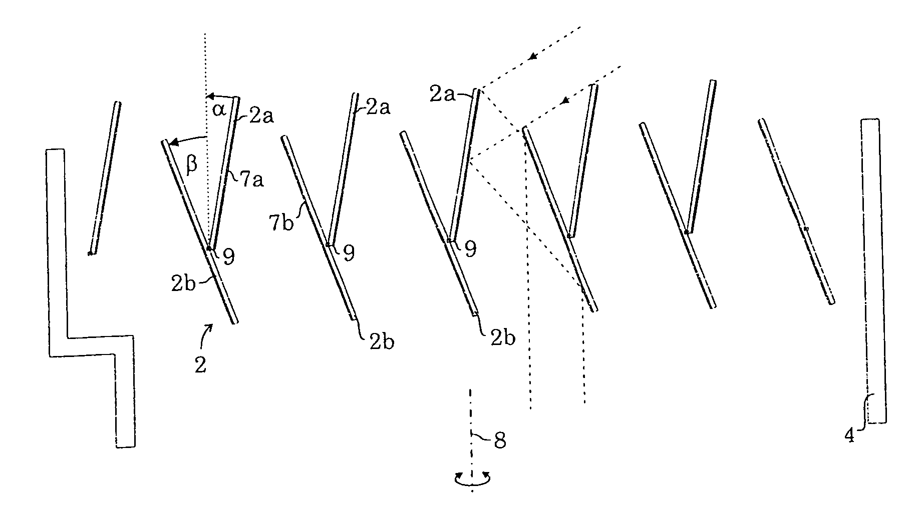
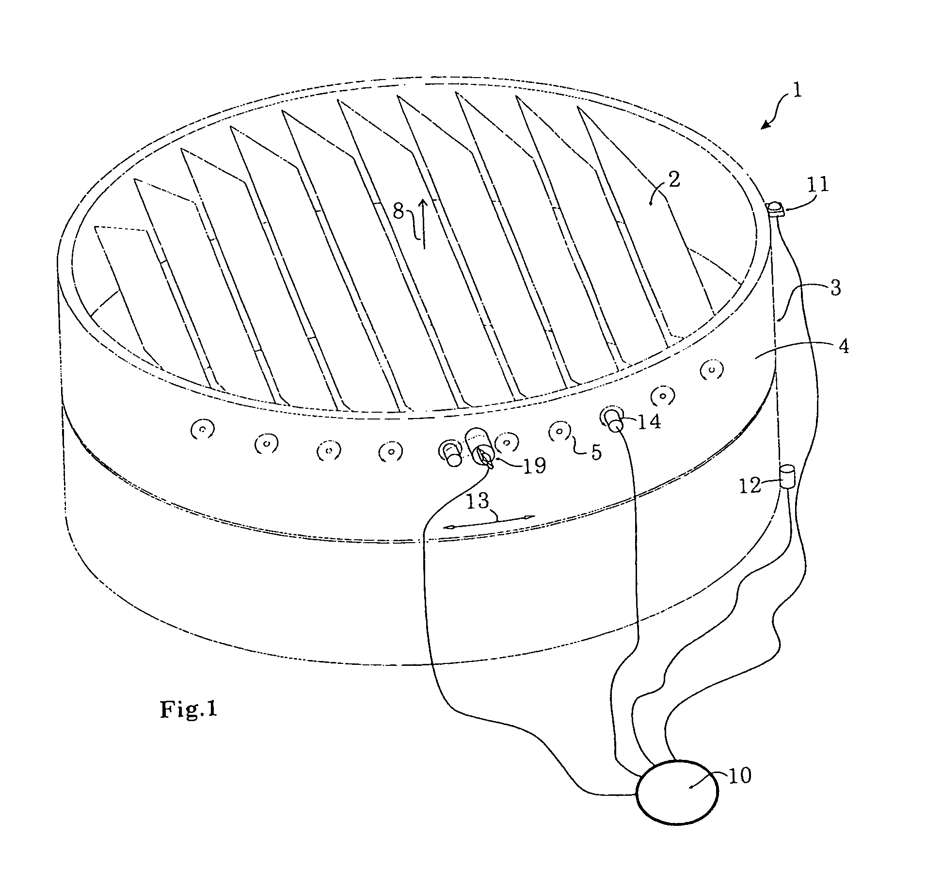
[0035]The light guide device 1 shown in FIG. 1 comprises an essentially cylindrical light guide tube portion 4 which may for example be located at the bottom of a light well or a light guide tube in order to guide the light into the interior of the building.

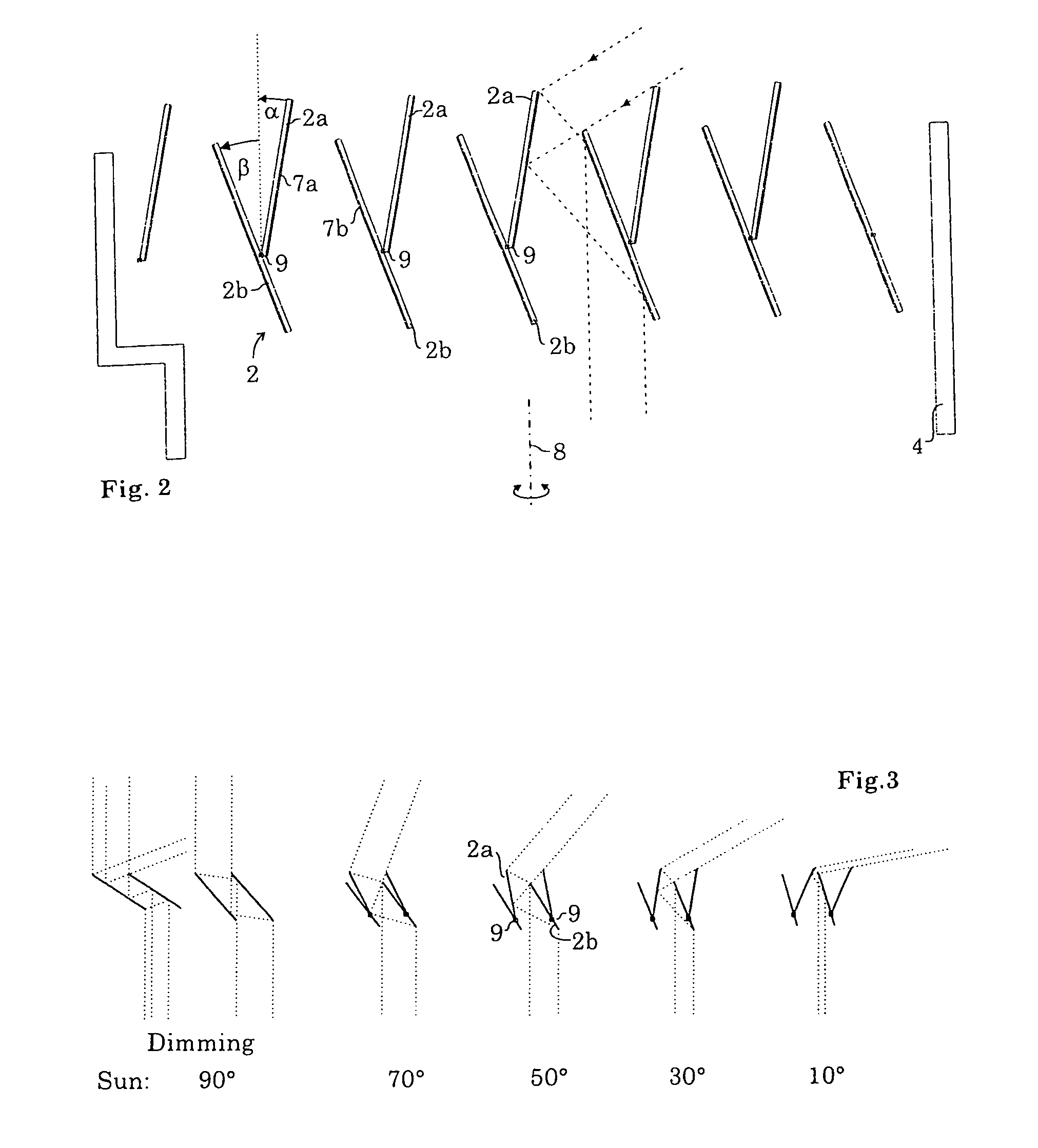
[0036]As it is shown in FIG. 6 the light guide device may be installed on top of the roof of a building. By the deflection of the captured sunlight by way of deflecting blades which are arranged in a parallel focused and in the downward direction essentially vertically aligned beam of sunlight significant advantages will arise in comparison to a conventional light tube. On the one hand efficiency will significantly increase, i.e. a much greater amount of light will reach the ground of the building in comparison to a conventional light tube as the number of reflections will significantly be reduced on the way down. While, with a conventional light tube, a multitude of reflections will arise on the walls until the light will reach ...


PUM


Abstract

The present invention relates to a light guide device for the introduction of sunlight into the interior of a building, having a multitude of movably mounted light deflection surfaces which are adjustable by control means depending on the position of the sun. According to the present invention the light deflecting surfaces of the light guide device are formed by serially arranged deflecting blades which may be swiveled about swivel axes which are approximately parallel to each other, the blades being mounted on a blade holder which is rotatable about a rotational axis which is essentially perpendicular to the direction of the swivel axes.

Description

CROSS-REFERENCE TO RELATED APPLICATIONS[0001]This application is a US National Stage of International Application No. PCT / EP2010 / 004627, filed 28 Jul. 2010, which claims the benefit of both DE 10 2009 035 451.4, filed 31 Jul. 2009, and DE 10 2009 039 136.3, filed 27 Aug. 2009, each herein fully incorporated by reference.FIELD OF THE INVENTION[0002]The present invention relates to a light guide device for the introduction of sunlight into the interior of a building, having a multitude of movably mounted light deflection surfaces which are adjustable by control means depending on the position of the sun.BACKGROUND OF THE INVENTION[0003]Due to the beneficial effects of natural daylight on human physiology and cognitive sensing architecture has been striving for some time to guide sunlight as deeply as possible into the interior of buildings in order to have a maximum of daylight even in rooms which are located in the interior side of a building and to require a minimum of artificial li...

Claims


Application Information

Patent Timeline
IPC IPC(8): G02B27/00F24S23/77
CPCF21V11/04F21S11/00Y02B10/20
Inventor BARTENBACH, CHRISTIAN
Owner BARTENBACH HLDG
Why Eureka
Try Eureka