
Torque controlled antagonistic shape memory alloy actuator

a technology of antagonistic shape memory and alloy actuator, which is applied in the direction of mechanical power devices, machines/engines, hot gas positive displacement engine plants, etc., can solve the problems of requiring interruption, reduced scale, and inability to adapt to use full size actuators which would be employed in actual vehicles

Active Publication Date: 2014-05-20
THE BOEING CO
View PDF17 Cites 25 Cited by
  • Summary
  • Abstract
  • Description
  • Claims
  • Application Information

AI Technical Summary

Benefits of technology

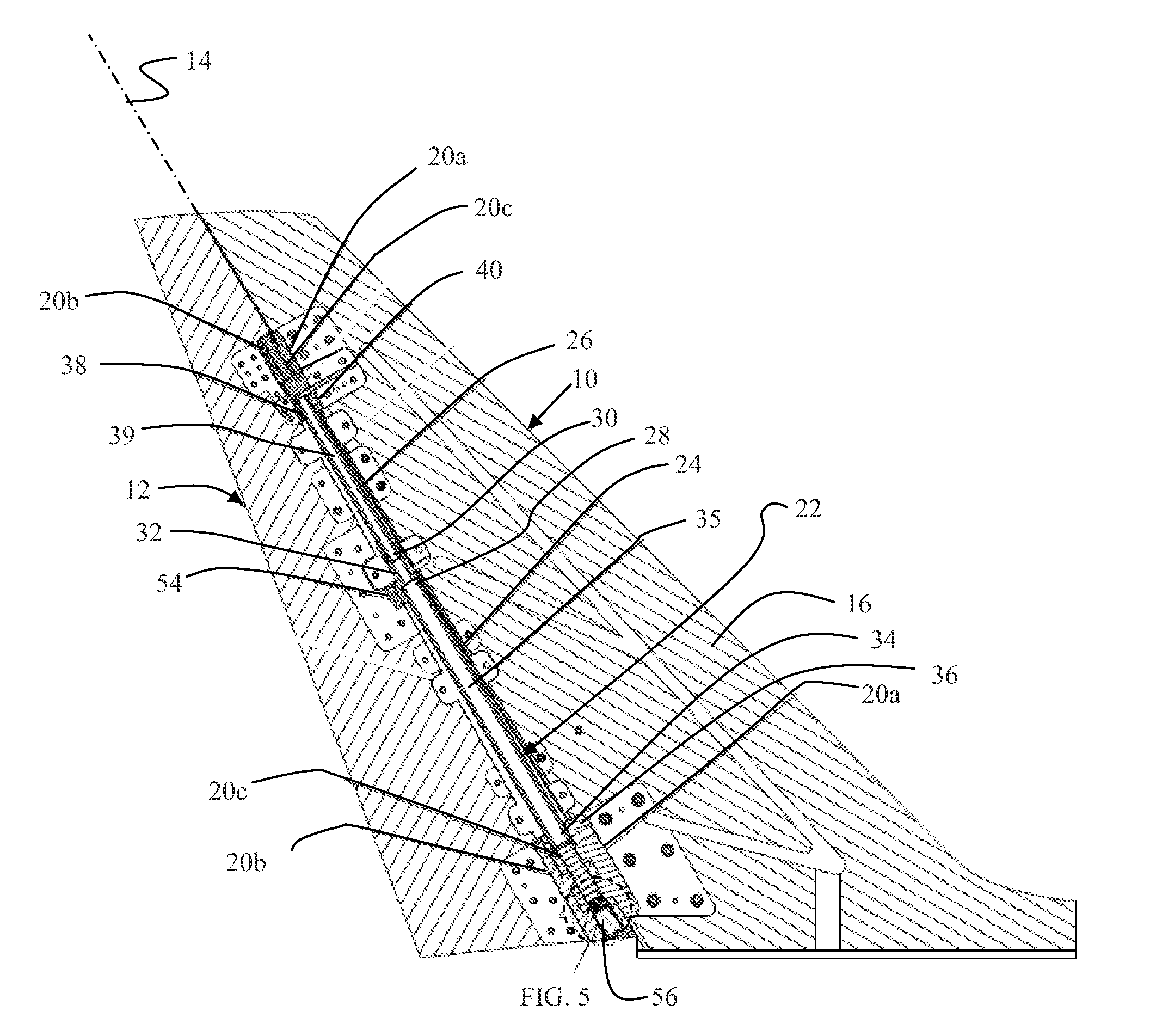
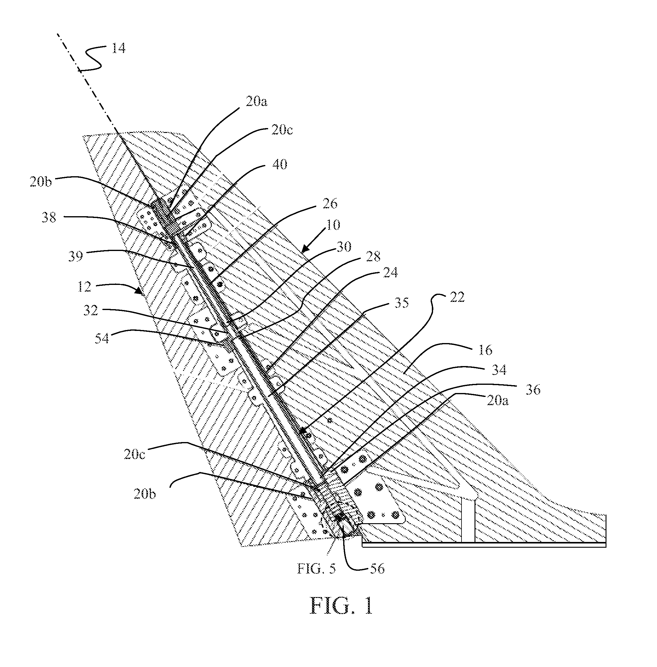
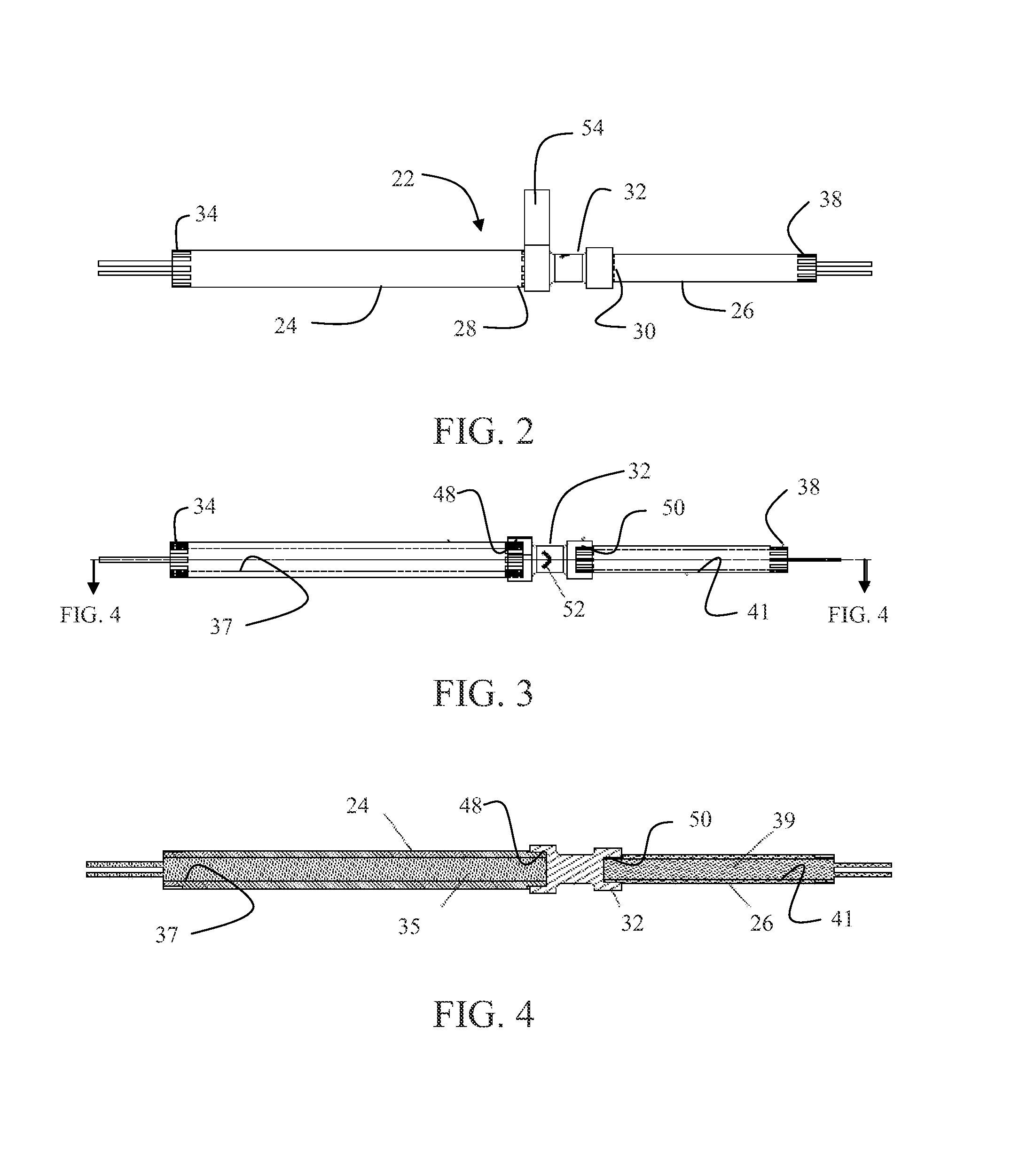
This patent describes a rotational actuator assembly that uses shape memory alloys for precise positioning and control of a central fitting. The assembly includes two torsion actuators with opposite trained twist directions and abutting proximal ends, joined at a central fitting with a control system using position sensors for both the drive torque actuator and the torque sensor for the return actuator. This allows for combined antagonistic rotation of the central fitting for accurate positioning and control. The technical effect of this design is a highly precise and efficient actuator for use in wind tunnel modeling and other applications requiring precise rotation.

Problems solved by technology

However, such surfaces must be positioned by hand requiring interruption of testing to position the surfaces at desired control angles.
Models are typically of reduced scale and therefore full size actuators which would be employed in actual vehicles are not readily adaptable for use.
However, electromechanical actuation is relatively bulky because of low power densities and the need for complex electric motor / gear assemblies.
As such, the amount of space required in the supporting structure (for example in a vertical tail) may limit the amount of instrumentation such as pressure sensors that can be installed in the model and may reduce the structural strength which tends to limit their use to lower pressure tunnels having lower loads.
Lower pressure tunnels do not match the aerodynamic characteristics of a full scale airplane as well which limits their fidelity as design tools for testing aircraft configurations.
SMA wire actuation has limited power and strength, and therefore is similarly suitable for low pressure wind tunnel testing only.
Frequently a spring solution becomes heavier and requires more volume than the SMA actuator reducing the most desirable characteristics of SMA actuators.

Method used


Image

  • Torque controlled antagonistic shape memory alloy actuator
  • Torque controlled antagonistic shape memory alloy actuator
  • Torque controlled antagonistic shape memory alloy actuator

Examples


Embodiment Construction

[0024]In aerodynamic control surfaces like spoilers, ailerons or rudder, the aerodynamic loading acts as a reversing load for a restoring force to a nominal streamlined position. An actuator solution to position these types of devices must be capable of applying force in both directions from nominal.

[0025]The embodiments described herein are detailed with respect to wind tunnel model use and for an arbitrary selection of positive and negative displacement. Alternative embodiments may be employed for aerodynamic or hydrodynamic control surfaces which experience a restoring force in motion and may provide symmetrical or asymmetrical positive and negative displacement of the surface. In general, the described embodiments provide an actuator that employs two shape memory alloy (SMA) tubes trained to twist in opposite directions as the tubes are heated. The tubes are centrally coupled together collinearly on the hinge line of the actuator. The ends of the tubes opposite the coupling are ...


PUM


Abstract

A rotational actuator assembly employs a drive torque actuator having a shape memory alloy (SMA) tube with a first trained twist direction and a return actuator having a SMA tube with an opposite trained twist direction collinear with the drive torque actuator with abutting proximal ends. A central fitting joins the proximal ends. A control system employs a position sensor for the drive torque actuator and the torque sensor for the return actuator for combined antagonistic rotation of the central fitting.

Description

REFERENCE TO RELATED APPLICATIONS[0001]This application is a continuation in part of application Ser. No. 12 / 880,004 entitled REMOTELY ACTUATED WIND TUNNEL MODEL RUDDER USING SHAPE MEMORY ALLOY filed on Sep. 10, 2010 having a common assignee with the present application, the disclosure of which is incorporated herein by reference as though fully set forth.BACKGROUND INFORMATION[0002]1. Field[0003]Embodiments of the disclosure relate generally to the field of control surface actuation systems and more particularly to embodiments for a shape memory alloy actuator with dual collinear shape memory alloy tubes having antagonistic reaction to form a smart spring return with a torque sensor.[0004]2. Background[0005]Wind tunnel models typically require movable control surfaces to allow simulation of various control aspects of the vehicle being modeled. Unmotorized surfaces are often used due to their simplicity. However, such surfaces must be positioned by hand requiring interruption of tes...

Claims


Application Information

Patent Timeline
Patent Type & Authority Patents(United States)
IPC IPC(8): B64C9/00F03G7/06
CPCF03G7/065
Inventor GUNTER, IAN, M.
Owner THE BOEING CO
Learn More