Moisture meter with non-contact infrared thermometer
What is Al technical title?
Al technical title is built by PatSnap Al team. It summarizes the technical point description of the patent document.
a thermometer and moisture meter technology, applied in the field of moisture meter, can solve the problem of reducing the ability to use the temperature-measuring devi
Active Publication Date: 2014-05-20
TELEDYNE FLIR LLC
View PDF31 Cites 24 Cited by
Summary
Abstract
Description
Claims
Application Information
AI Technical Summary
This helps you quickly interpret patents by identifying the three key elements:
Problems solved by technology
Method used
Benefits of technology
[0009]It is therefore an object of this invention to provide an instrument that can be used to measure both moisture parameters and remote temperature. Many of the functions of these measurements, such as the display, power supply, housing, and analog to digital converter, can be common to both the moisture meter and the surface temperature measurement functionality. With this invention, portability is improved by only having to carry one instrument for use in the field. To further simplify use for quick field measurements, in a preferred embodiment there is no need to relocate the moisture enclosure from the temperature measurement function.
[0013]Featured in another embodiment is a moisture meter with non-contact temperature measurement capability, comprising a contact-type first moisture-detecting device contained at least partially in a housing and having an output related to measured moisture parameters, a penetrating pin-type second moisture-detecting device in a hand-held probe that is separate from the housing and is connected to the housing by a cord to make electrical contact with circuitry in the housing, the second moisture-detecting device having an output related to measured moisture parameters, an ambient temperature sensor and an ambient humidity sensor located in a probe that is coupled to and extends from the housing, a non-contact, infrared sensor temperature sensing device coupled to the housing, having an output related to sensed temperature, an optical aiming device coupled to the housing, to assist the user in aiming the non-contact temperature-sensing device at an object whose temperature is to be measured, an output display contained in the housing, for displaying measurements to a user, and circuitry contained in the housing for processing both of the moisture device outputs, and the humidity and the temperature sensing device outputs, and transmitting the processed outputs to the output display. The non-contact temperature-sensing device may define a sense axis that is fixed relative to the housing. The housing may have a rear side, and the contact-type first moisture-detecting device may comprise a pad on the rear side of the housing.
Problems solved by technology
However, this prevents or reduces the ability to use the temperature-measuring device to make a contact-type temperature measurement.
In addition, very often there is a need to measure surface temperatures of surfaces that cannot be easily accessed with a contact type-measuring device.
Method used
Image
Click on the blue label to locate the original text in one second.
Reading with bidirectional positioning of images and text.
Examples
Embodiment Construction
[0020]In the invention, the common functions required for processing of signals from an infrared (IR) temperature sensor, a digital moisture meter, a humidity sensor and a temperature sensor, are accomplished by common circuitry, and a common display and other parts as described herein.
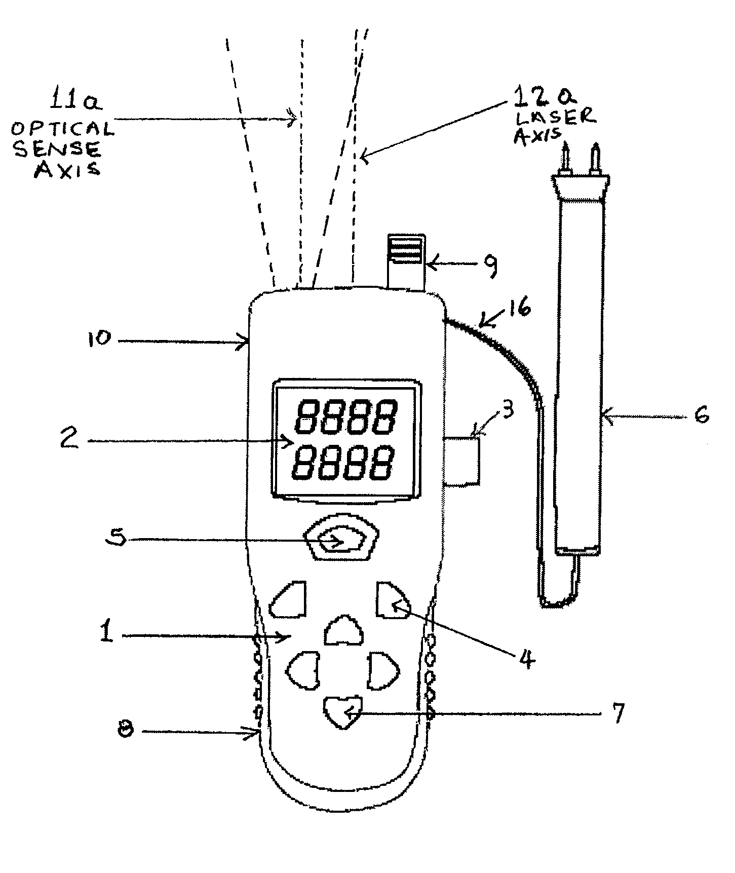
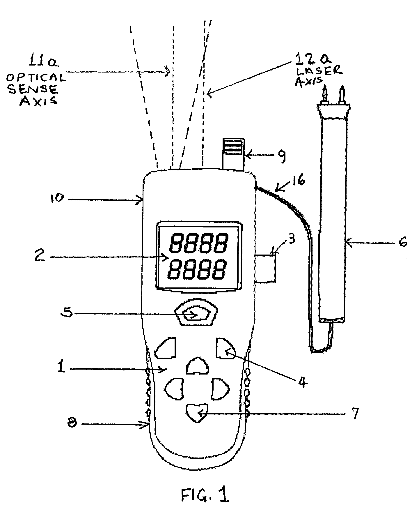
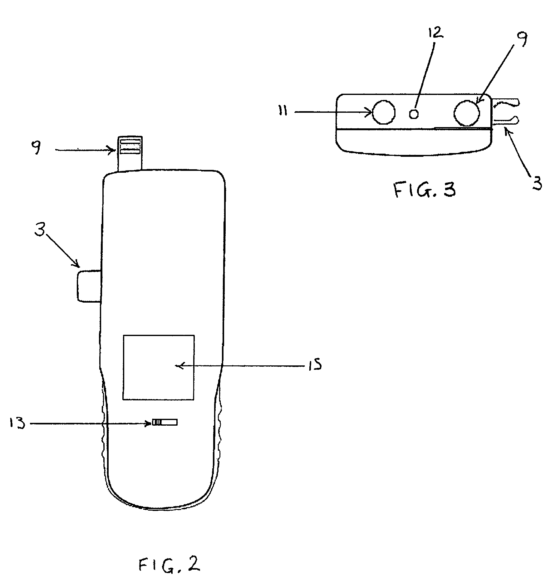
[0021]A typical mechanical arrangement of moisture meter 10 of the invention is shown in FIGS. 1-4. FIG. 1 is a front view of a typical arrangement consisting of a housing or case 1 that contains the circuitry in a convenient hand-held unit, with a dual readout digital display 2 for reading the values being measured. Pushbutton switches 4 allow the user to select one of a multiplicity of functions with a multiplicity of ranges. Pushbutton switches 4 perform further selection of parameters or functions, in combination with pushbuttons 7, for example those related to the ambient temperature measurement. Pushbutton switch 5 can be used to turn on the laser-aiming device. In other embodiments, this pushbu...
PUM
Property
Measurement
Unit
emissivities
aaaaa
aaaaa
emissivity
aaaaa
aaaaa
temperature
aaaaa
aaaaa
Abstract
A moisture meter with non-contact temperature measurement capability having a housing, a moisture-detecting device coupled to or contained at least partially in the housing, and having an output related to measured moisture parameters, a non-contact, optically-based temperature sensing device coupled to the housing, having an output related to sensed temperature, an output display contained in the housing, for displaying measurements to a user, and circuitry contained in the housing for processing both the moisture-detecting device output and the non-contact temperature sensing device output, and transmitting the processed outputs to the output display. The moisture-detecting device can be either one or both of a contact-type moisture-detecting device such as a pad on the rear side of the housing, and a pin-type moisture-detecting device in a hand-held probe, and electrically coupled to the circuitry in the housing through a cord.
Description
RELATED U.S. PATENT AND APPLICATION DATA[0001]The present application is a Continuation-in-Part of and claims the benefit of non-provisional U.S. patent application Ser. No. 11 / 189,122, “Anemometer with Non-Contact Temperature Measurement,” filed Jul. 25, 2005, now U.S. Pat. No. 7,452,127;[0002]U.S. patent application Ser. No. 11 / 189,122 is a Continuation-in-Part of and claims the benefit of U.S. patent application Ser. No. 11 / 039,653, “Humidity Meter with Non-Contact Temperature Measurement,” filed Jan. 19, 2005, now U.S. Pat. No. 7,168,316;[0003]U.S. patent application Ser. No. 11 / 189,122 is also a Continuation-in-Part of and claims the benefit of U.S. patent application Ser. No. 10 / 910,894, “Instrument for Non-Contact Infrared, Temperature Measurement Having Current Clamp Meter Functions,” filed Aug. 4, 2004 now U.S. Pat. No. 7,163,336;[0004]U.S. patent application Ser. No. 11 / 189,122 is also a Continuation-in-Part of and claims the benefit of U.S. patent application Ser. No. 10 / ...
Claims
Application Information
Patent Timeline
Application Date:The date an application was filed.
Publication Date:The date a patent or application was officially published.
First Publication Date:The earliest publication date of a patent with the same application number.
Issue Date:Publication date of the patent grant document.
PCT Entry Date:The Entry date of PCT National Phase.
Estimated Expiry Date:The statutory expiry date of a patent right according to the Patent Law, and it is the longest term of protection that the patent right can achieve without the termination of the patent right due to other reasons(Term extension factor has been taken into account ).
Invalid Date:Actual expiry date is based on effective date or publication date of legal transaction data of invalid patent.