Eureka AIR delivers breakthrough ideas for toughest innovation challenges, trusted by R&D personnel around the world.

Shredding device

Active Publication Date: 2014-05-27
LINDNER RECYCLINGTECH
View PDF8 Cites 4 Cited by
  • Summary
  • Abstract
  • Description
  • Claims
  • Application Information

AI Technical Summary

Benefits of technology

The shredding device described in this patent has a pusher device that is fully installed in the material charging compartment of the shredding device. This pusher device remains in direct contact with the material to be pressed towards the rotor during shredding operation. The pusher surface is not pivoted or guided towards the outside of the material charging compartment, but rather remains within it, ensuring an enclosed construction of the shredding device and minimizing disturbance caused by waste products. The shredding device can also be partially pivoted out of the material charging compartment for maintenance purposes, allowing easy access to the pusher surface without having to enter the shredding device.

Problems solved by technology

These guides however inevitably become soiled in the course of the shredding operation and this can interfere with proper shredding operation.
In addition the draw-type pusher increases the space required by the shredding device.
Also with this embodiment the space requirement is disadvantageously relatively high.
In addition the sealing of the compression element passed through the aperture is problematical, because even if the press platen is pivoted without guidance for compression, waste products can gain access to the edges of the aperture, thus severely hindering the pushing process.

Method used


Image

  • Shredding device
  • Shredding device
  • Shredding device

Examples


Embodiment Construction

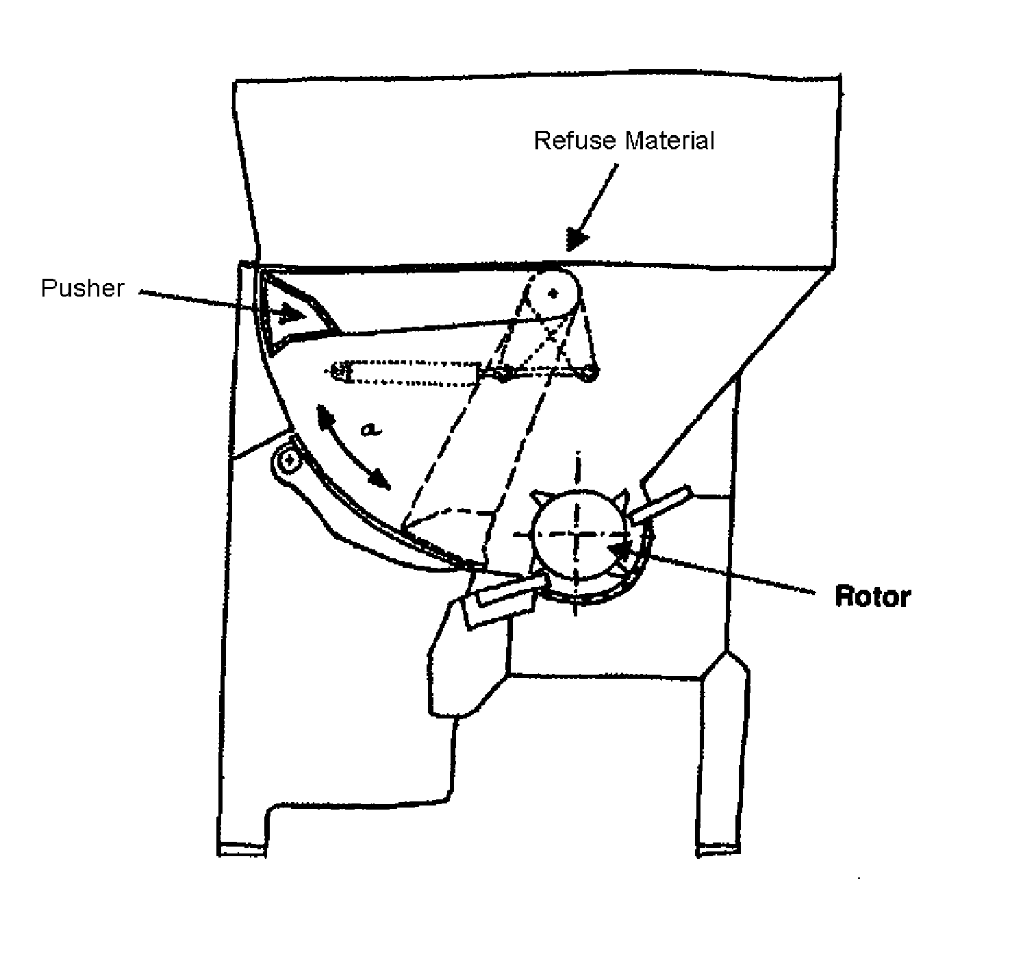
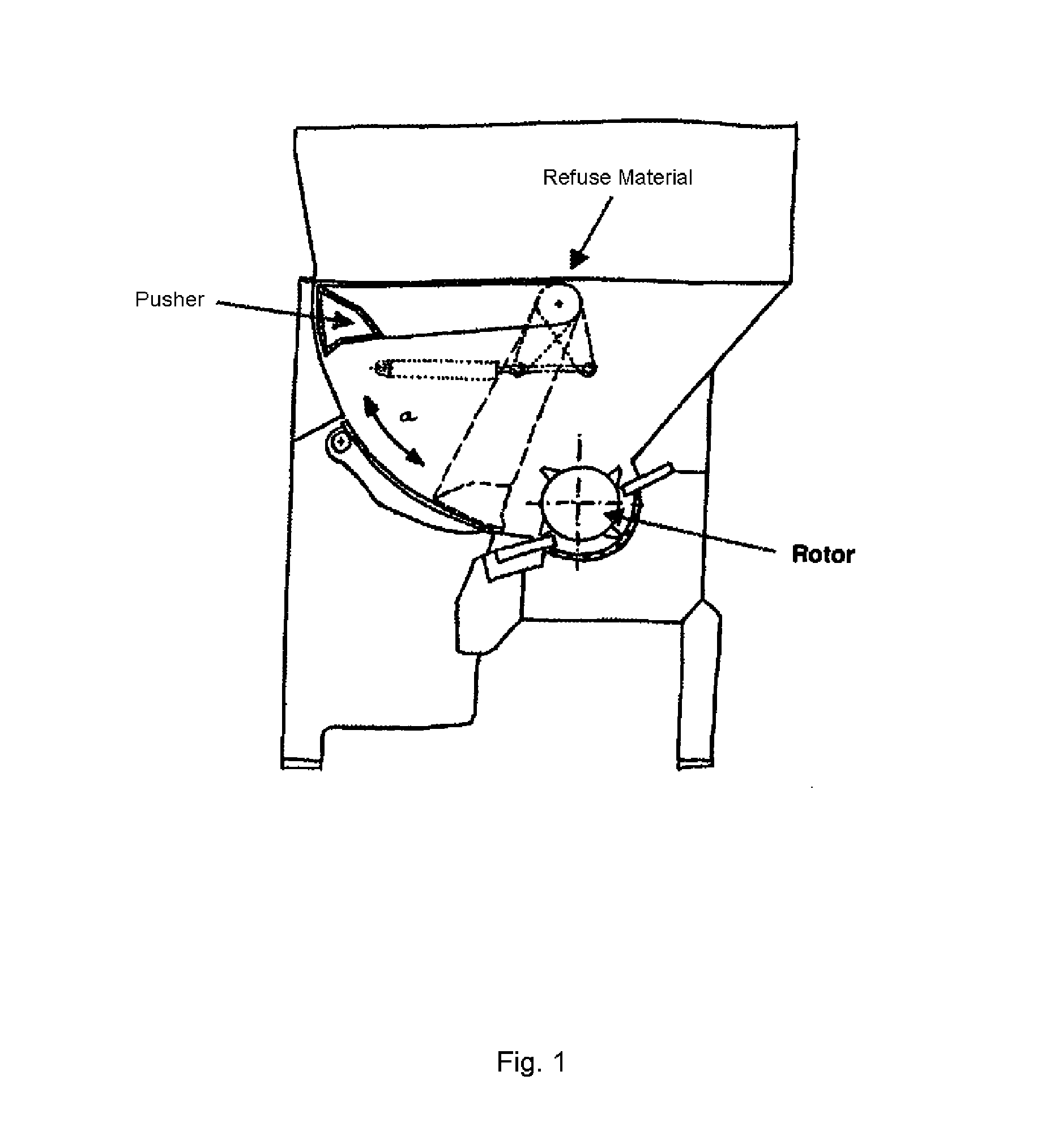
[0028]As illustrated in FIG. 1, in accordance with the present invention an exemplary vertical shredder comprises a rotor for shredding refuse material with blades interacting with stationary counter-blades, which are mounted on the shredder housing at both ends of the rotor. The shredded material is ejected through a sieve device fitted below the rotor and extending between the counter-blades.

[0029]In operation a pusher completely installed in the material charging compartment of the shredding machine pushes charged refuse material using pivoting movements against the rotating rotor. Two operating states of the pusher are illustrated in FIG. 1 by continuous or broken outlines of it. In the illustrated example the pusher has a pusher surface a formed concavely with respect to the material to be pressed in the direction towards the rotor.

[0030]The angular range between an operating state in which the pusher surface is located the furthest away from the rotor and an operating state in...


PUM


Abstract

The present invention relates to a shredding device for shredding material, comprising a material charging compartment in which the material to be shredded can be loaded; a rotor; and a pusher device having a pusher and a drive device for the pusher, wherein the pusher is pivotable about an axis such that it presses the material to be shredded towards the rotor, and wherein the pusher remains completely within the material charging compartment during operation.

Description

FIELD OF THE INVENTION[0001]The present invention relates to a shredding device for shredding material, particularly in the form of waste products and in particular a shredding device with a pusher device.BACKGROUND OF THE INVENTION[0002]Commercial, industrial, and household waste, e.g. (rigid) plastics, textiles, composites, rubber and used wood (such as pallets and chipboard), needs to be reduced in size before its final disposal or in particular before return to the recycling system. For shredding single or multi-shaft shredding machines are known, which for example are charged by wheel loaders, fork-lift trucks or conveyor belts via a hopper for charging material.[0003]A central element of a conventional shredding machine is a rotor unit, which comprises a rotor which is fitted with tearing hooks or blades, which, for example, can be provided with concavely ground round cutter crowns. The blades are mounted for example by screwing onto blade bearers which are welded into or bolt...

Claims


Application Information

Patent Timeline
IPC IPC(8): B02C18/22
CPCB02C18/14B02C18/2275B02C18/0084B30B9/301B02C18/2233
Inventor SCHIFFER, PETER
Owner LINDNER RECYCLINGTECH
Why Eureka
Eureka Blog
Learn More