Flash memory with bias voltage for word line/row driver

a technology of flash memory and word line/row driver, which is applied in the field of nonvolatile memory, can solve the problem of requiring additional time to stabilize the word line voltag

Active Publication Date: 2014-05-27
NXP USA INC
View PDF10 Cites 99 Cited by
  • Summary
  • Abstract
  • Description
  • Claims
  • Application Information

AI Technical Summary

Problems solved by technology

The setup time to drive the bias voltage creates a transient while the mirror requires time to stabilize the current, thereby requiring additional time to stabilize the word line voltage.

Method used


Image

  • Flash memory with bias voltage for word line/row driver
  • Flash memory with bias voltage for word line/row driver
  • Flash memory with bias voltage for word line/row driver

Examples


Embodiment Construction

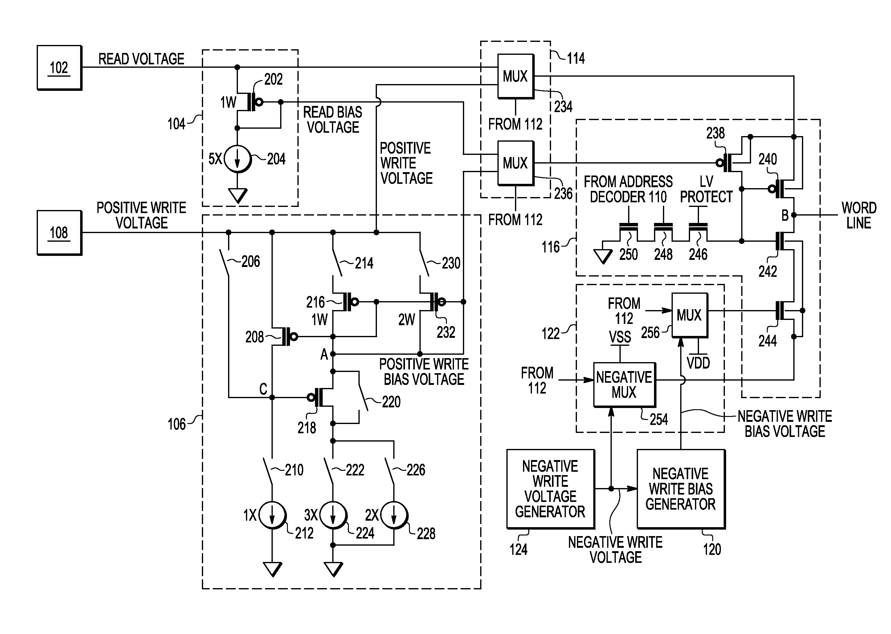
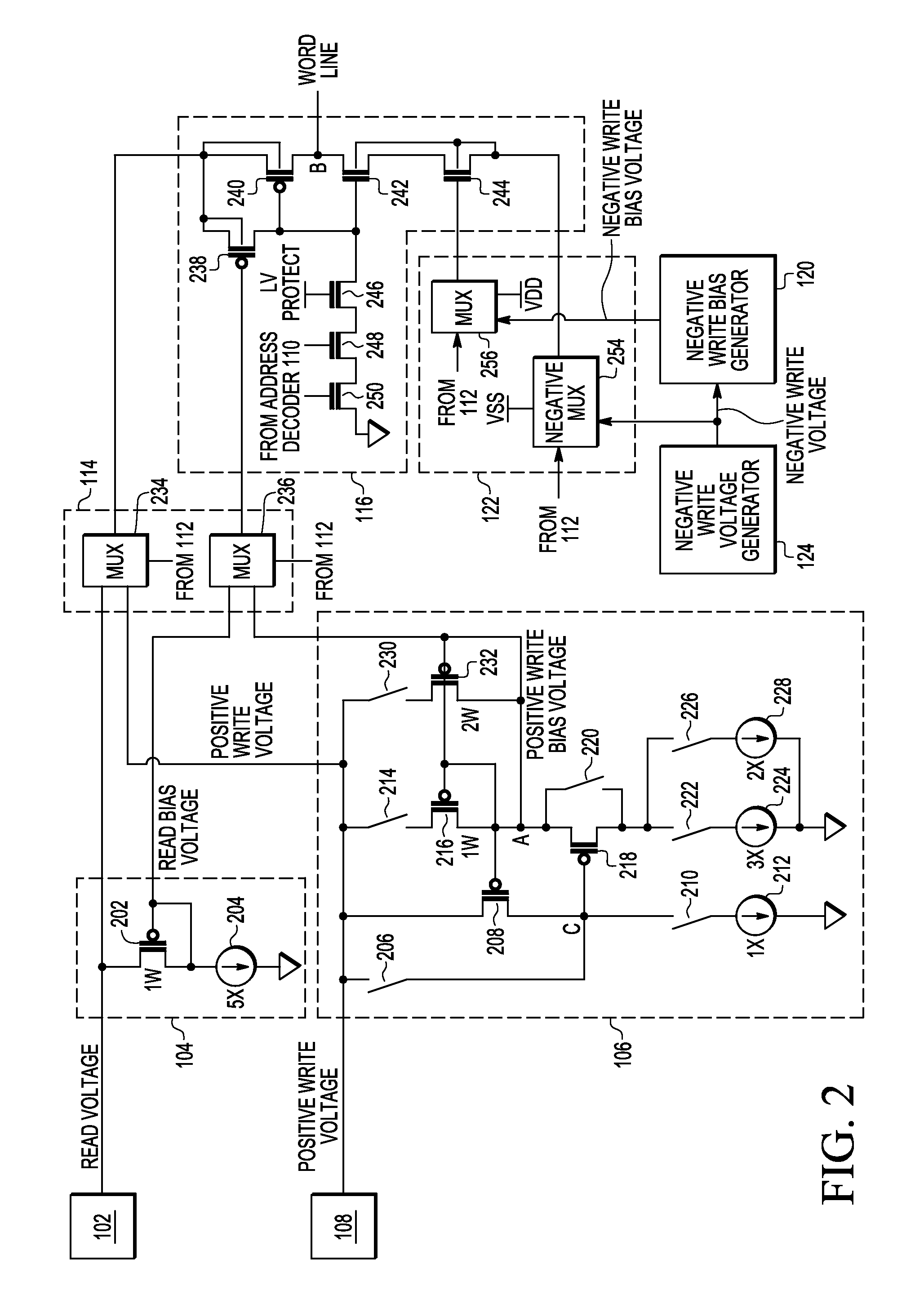
[0011]Embodiments of devices and methods are disclosed that provide write bias voltage to limit current in a word line driver during write operations. The write bias voltage is used in a word line driver circuit to stabilize word line signals at a desired voltage more quickly and enable faster operation of the memory cells as a result.

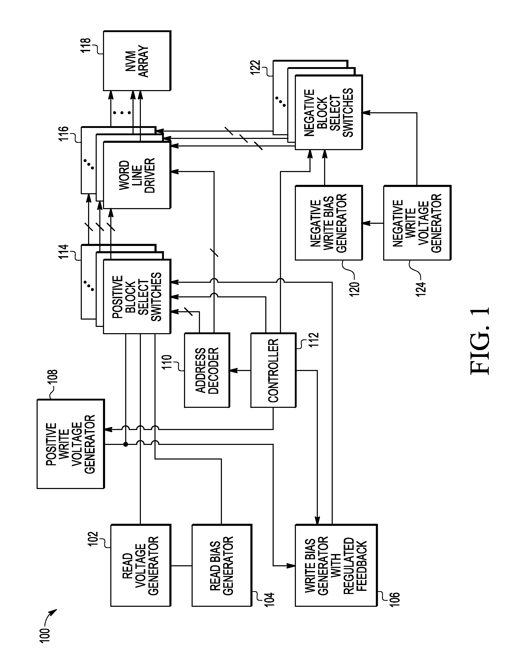
[0012]FIG. 1 is a block diagram of an embodiment of a non-volatile memory (NVM) device 100 in accordance with the present disclosure including read voltage generator or node 102, read bias generator or node 104, write bias generator or node with regulated feedback 106, positive write voltage generator or node 108, address decoder 110, controller 112, positive block select switches 114, word line drivers 116, non-volatile memory array 118, negative write bias generator or node 120, negative block select switches 122, and negative write voltage generator or node 124.

[0013]Read voltage generator 102 is coupled to supply read voltage to read bias generator...


PUM


Abstract

A memory device includes a word line driver circuit, a write voltage generator for providing a write voltage to the word line driver during a write operation to memory cells coupled to the word line driver circuit, and a write bias generator including an output node for providing a write bias voltage that is different from the write voltage to the word line driver circuit during a write operation to memory cells coupled to the word line driver circuit. The write bias voltage is used to reduce current drawn by the word line driver circuit from the write voltage generator during a write operation to memory cells coupled to the word line driver circuit.

Description

BACKGROUND[0001]1. Field[0002]This disclosure relates generally to non-volatile memory, and more specifically, to generating a voltage bias for word line / row drivers.[0003]2. Related Art[0004]Non-volatile memory (NVM) such as electrically-erasable programmable read-only memory (EEPROM) and flash uses different levels of voltages at first and second current terminals and control gate during read, write, erase, and write verify operations. The highest levels of voltage are typically used during write operations. The voltages in the NVM device are generated by voltage generators and are supplied to driver circuits that are coupled to selected memory cells in an array of memory cells. The driver circuits pull current against a load device. The load is limited by mirroring a bias voltage to the driver circuits. The setup time to drive the bias voltage creates a transient while the mirror requires time to stabilize the current, thereby requiring additional time to stabilize the word line ...

Claims


Application Information

Patent Timeline
Patent Type & Authority Patents(United States)
IPC IPC(8): G11C16/06
CPCG11C8/08G11C16/08
Inventor CHOY, JON S.SANJEEVARAO, PADMARAJ
Owner NXP USA INC
Why Eureka
Try Eureka