Method and system for asynchronous lamp identification

a technology of asynchronous lamp identification and method, which is applied in the field of illumination system and optical receiver, can solve the problems of increasing complexity and cost of illumination system

Inactive Publication Date: 2014-05-27
SIGNIFY HLDG BV +1
View PDF47 Cites 14 Cited by
  • Summary
  • Abstract
  • Description
  • Claims
  • Application Information

AI Technical Summary

Benefits of technology

[0015]In one embodiment, the first shifted base code within the first information code may be immediately preceded by or immediately followed by the synchronization code. In another embodiment, the information signal may comprise one synchronization code immediately preceded or immediately followed by two or more of the first shifted base codes. In yet another embodiment, there may be a sequence of one or more binary values between the synchronization code and the first shifted base code (such a sequence is referred herein as a “spacer sequence”). For example, there may be a spacer sequence of zeros between the synchronization code and the first shifted base code. Inserting such a spacer sequence may decrease, simplify, and / or improve the accuracy of data processing necessary for retrieving the first data at the receiver. In yet another embodiment, the first information signal may comprise an alternating sequence of one or more of the first shifted base codes and the synchronization codes.
[0020]The embodiment of claim 3 advantageously allows embedding more data. For example, when the data comprises identification of the light source and the base code comprises N binary values, embodiment of claim 3 allows identifying 2N different light sources.
[0022]The embodiment of claim 5 allows additional data to be embedded into the luminance output by embedding this data into the signs of the different shifted base codes within the information signal. The additional data may comprise e.g. data related to the temperature or the dimming levels of the first light source. In one embodiment, the first information signal may comprise a second shifted base code immediately preceding or immediately following the first shifted base code. In such an embodiment, data throughput may be advantageously maximized by decreasing the frequency of occurrence of the synchronization code.

Problems solved by technology

However, most of the previous implementations require some kind of synchronization between the different light sources.
Such a synchronization requires additional hardware, increasing complexity and cost of the illumination system.

Method used


Image

  • Method and system for asynchronous lamp identification
  • Method and system for asynchronous lamp identification
  • Method and system for asynchronous lamp identification

Examples


Embodiment Construction

[0038]In the following description, numerous specific details are set forth to provide a more thorough understanding of the present invention. However, it will be apparent to one of skill in the art that the present invention may be practiced without one or more of these specific details. In other instances, well-known features have not been described in order to avoid obscuring the present invention.

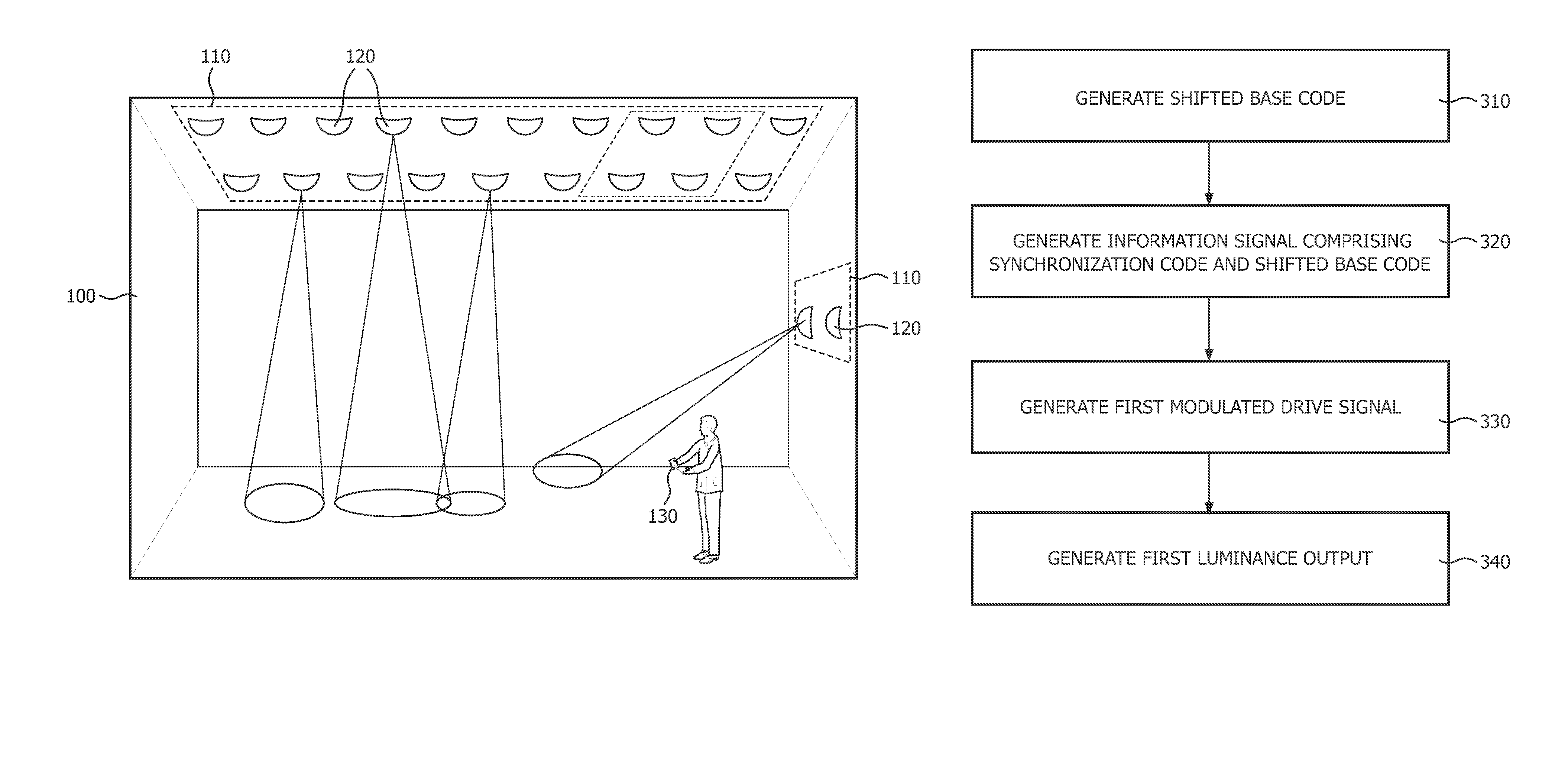
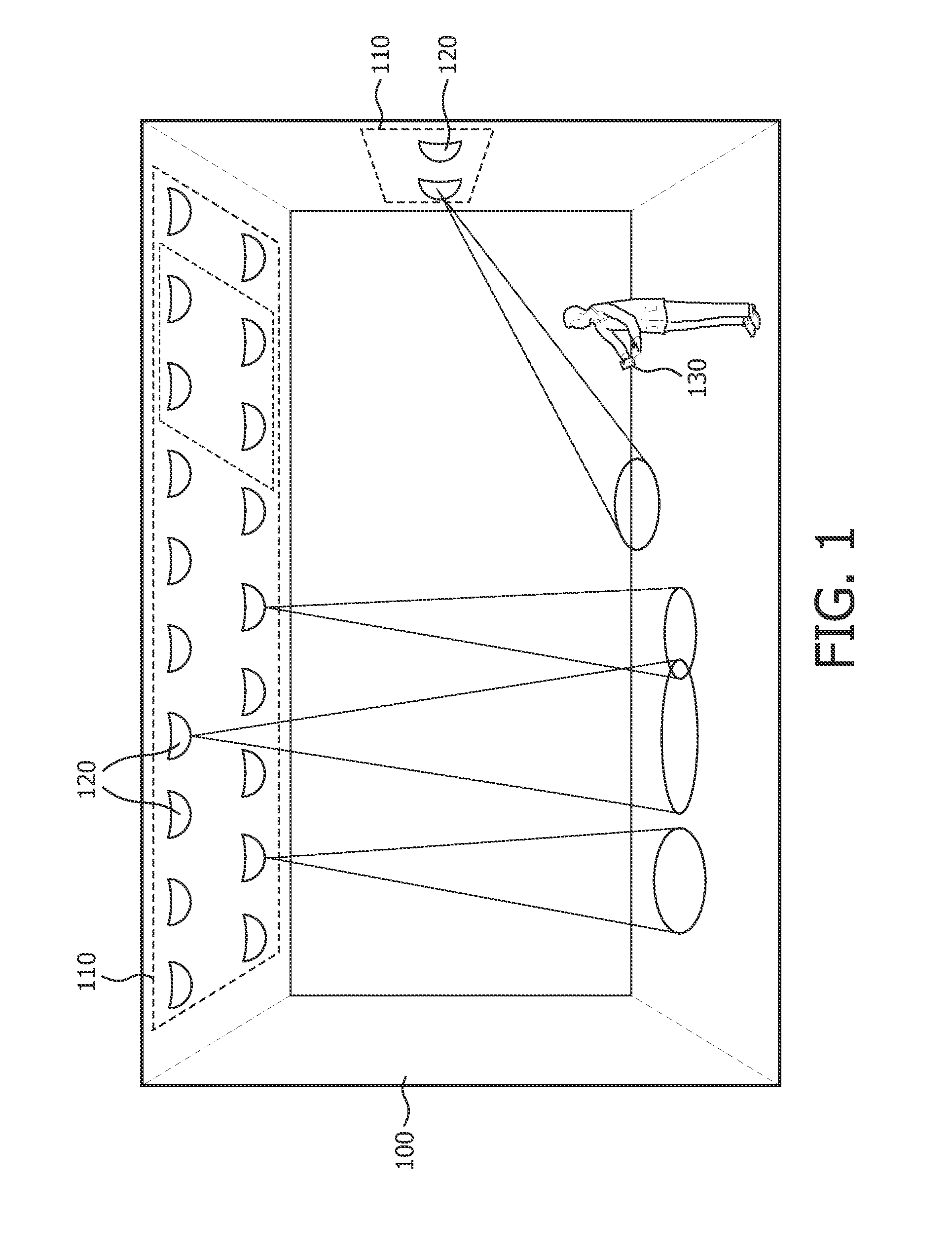
[0039]FIG. 1 shows a structure 100—in this case a room—with an installed illumination system 110. The illumination system 110 comprises one or more of light sources 120 and one or more controllers (not shown in FIG. 1) controlling the light sources 120. The light sources 120 may comprise high / low pressure gas discharge sources, inorganic / organic light emitting diodes, laser diodes, incandescent sources, or halogen sources. The illumination system 110 may further comprise a remote control 130 allowing a user to control the light sources 120.

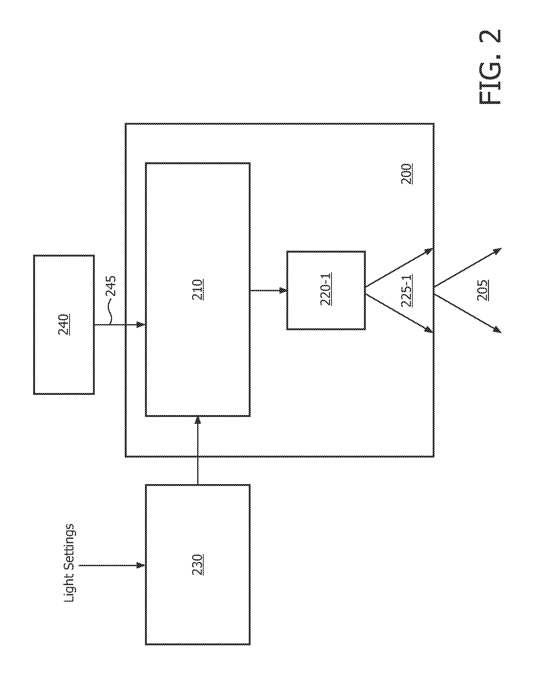
[0040]FIG. 2 is a schematic illustration of an ...


PUM


Abstract

The invention relates to embedding data into a luminance output generated by an illumination system comprising a light source and a controller. The controller is configured to embed data by modulating a drive signal applied to the light source with an information signal comprising a shifted base code and a synchronization code. The synchronization code serves to provide synchronization for the receiver, while the shifted base code serves to carry the embedded data. A cyclic phase shift that is applied to a base code to generate the shifted base code corresponds to particular data, such as, for example, light source identification, that needs to be embedded into the luminance output of the illumination system. In this manner, data may be embedded into the luminance output generated by a light source without requiring synchronization of this light source with other light sources.

Description

FIELD OF THE INVENTION[0001]Embodiments of the present invention relate generally to the field of illumination systems and optical receivers, and, more specifically, to systems and methods for embedding data into the luminance output of such illumination systems.DESCRIPTION OF THE RELATED ART[0002]In recent years, highly advanced illumination systems are being developed that allow consumers to obtain a desired ambiance for a particular room or space. These illumination systems move away from the traditional control of individual light sources (switching on / off and dimming) to scene setting, where sets of light sources are controlled simultaneously. An example of such an illumination system is an arrangement of several sets of light sources in a room, a lobby or a vehicle.[0003]For these scene setting applications, intuitive user interaction is identified as one of the most important success factors. Providing a user with information related to the light sources, such as localized id...

Claims


Application Information

Patent Timeline
Patent Type & Authority Patents(United States)
IPC IPC(8): H04B10/00H05B44/00
CPCH05B33/0863H05B37/0272H04B10/116H05B45/20H05B47/19H05B45/10
Inventor SCHENK, TIM CORNEEL WILHELMUSFERI, LORENZOTALSTRA, JOHAN CORNELIS
Owner SIGNIFY HLDG BV
Why Eureka
Try Eureka