Circular saw

a circular saw and saw blade technology, applied in the field of circular saws, can solve the problems of small tooth face area, easy wear of gears, and small wear resistance of gears, and achieve the effect of smoother cutting operation

Inactive Publication Date: 2014-06-03
MAKITA CORP
View PDF33 Cites 800 Cited by
  • Summary
  • Abstract
  • Description
  • Claims
  • Application Information

AI Technical Summary

Benefits of technology

[0008]According to a preferred aspect of the invention, the circular saw further includes an input shaft which is driven by the power source, and the input shaft is connected to the first rotating shaft by engagement of gears, while the second rotating shaft comprises an output shaft of the saw blade. The circular saw is of a parallel three-shaft type in which the input shaft is also disposed parallel to the parallel first and second rotating shafts. Specifically, in this construction, the three shafts, or the input shaft, the output shaft of the saw blade in the form of the second rotating shaft and the intermediate shaft in the form of the first rotating shaft disposed between the input shaft and the output shaft. With such a construction, gears are engaged between the input shaft and the first rotating shaft and between the first rotating shaft and the second rotating shaft, so that the variety of settings of the speed reduction ratio can be increased compared with a construction using a speed reducing structure formed only by the first and second rotating shafts.
[0020]According to the invention, smoother cutting operation can be realized by allowing smooth control of the cutting speed of a saw blade within the circular saw.

Problems solved by technology

Particularly, in the case of a construction in which gears to be engaged are shifted for speed change by sliding gears along a shaft, like the known speed change mechanism, a rattle may be caused due to a clearance between mating surfaces of the shaft and the gears, so that wear is easily caused and the gears have a problem in durability.
Further, during shift of engagement of the gears, on the verge of disengagement of the gears and in the early stage of engagement of the gears, a very small area of a tooth face is subjected to torque, so that a problem in strength, such as chipping and wear of the teeth, arises.
Further, when the gears are engaged, noise may also be caused due to interference of the teeth.

Method used


Image

  • Circular saw
  • Circular saw
  • Circular saw

Examples


first embodiment

of the Invention

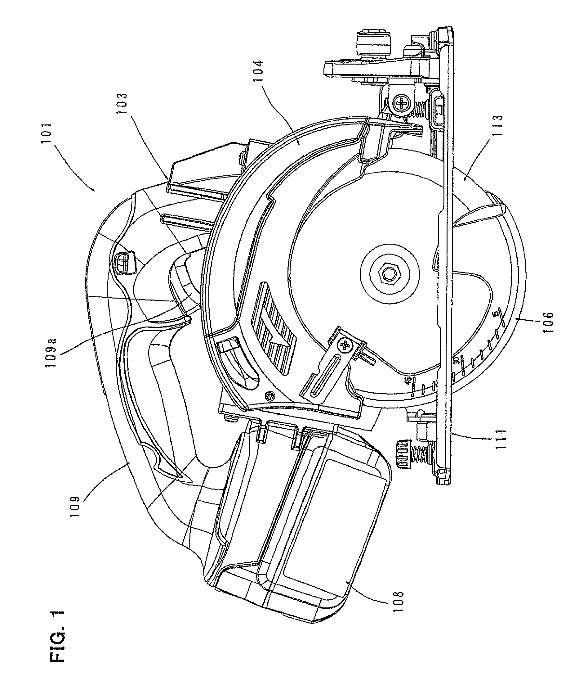
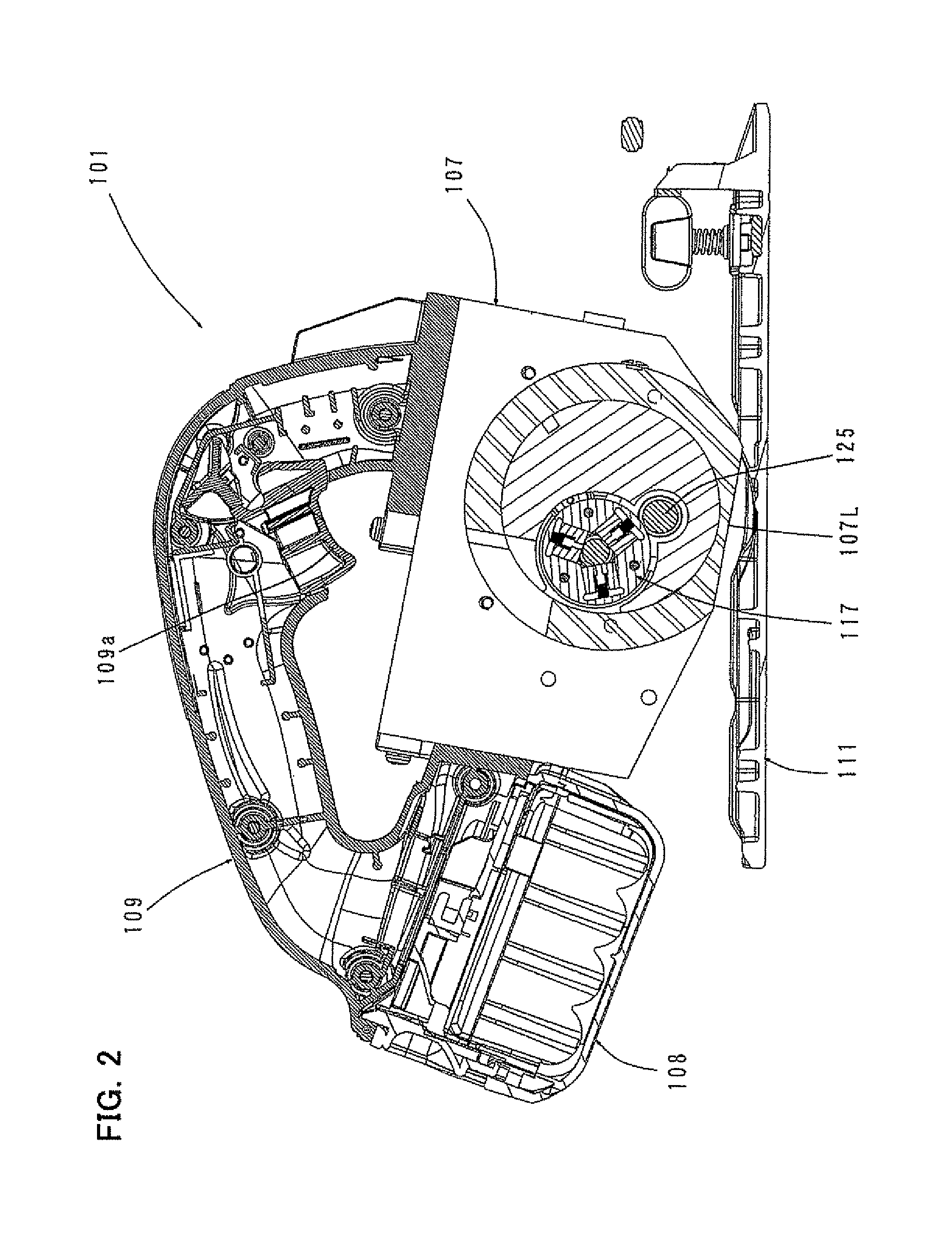
[0049]A first embodiment of the invention is now explained with reference to the drawings. A battery-powered circular saw (also referred to as a power tool) having a battery is now explained as a representative embodiment of the “circular saw” according to the invention. FIG. 1 is a side view showing an entire circular saw 101 according to this embodiment. FIG. 2 is a sectional side view of the entire circular saw 101. FIG. 3 is a sectional front view of the entire circular saw 101. As shown in FIGS. 1 to 3, the circular saw 101 according to this embodiment includes a base 111 which can be placed on a workpiece (not shown) and moved in a cutting direction, and a circular saw body 103 disposed above the base 111.

[0050]The circular saw body 103 mainly includes a blade case 104 that covers substantially an upper half of a disc-like blade (saw blade) 113 which is rotated in a vertical plane, a motor housing 105 that houses a driving motor 115, a gear housing 107 that hou...

second embodiment

of the Invention

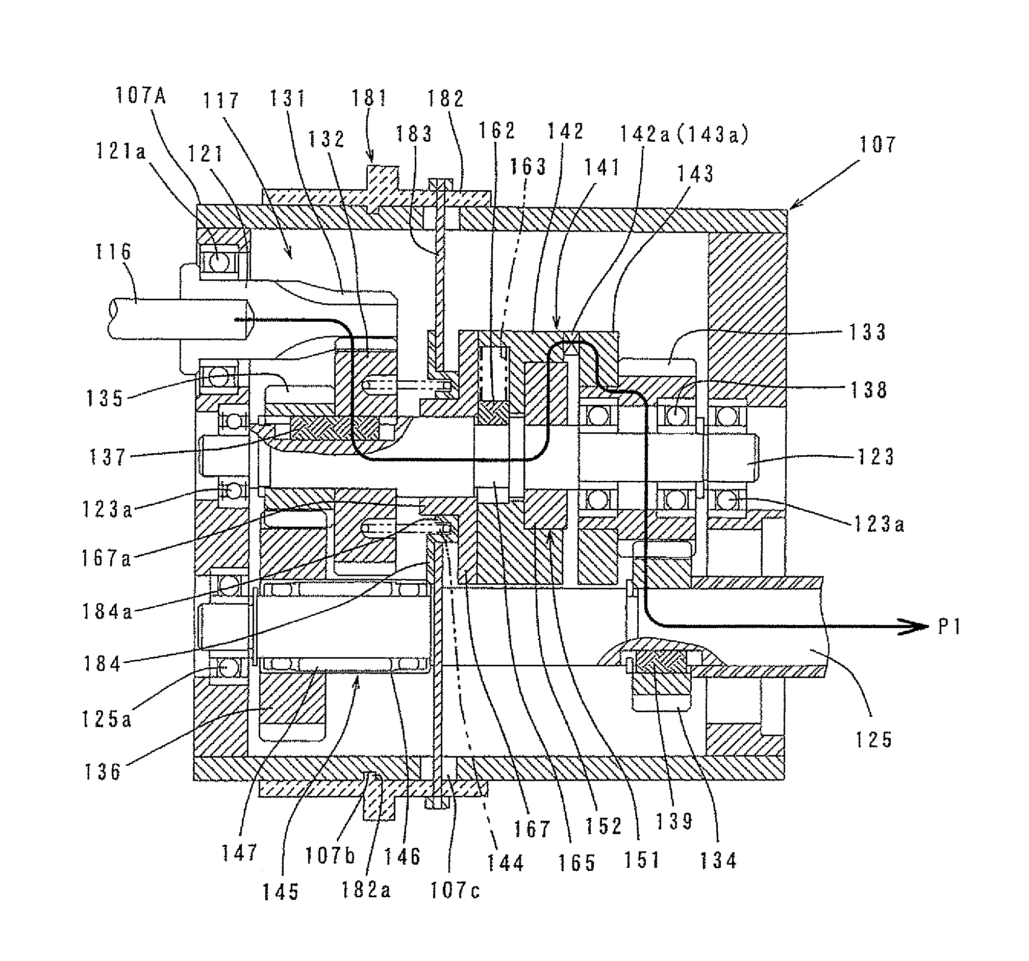
[0103]A second embodiment of the invention is now explained with reference to FIGS. 22 and 23. FIG. 22 is an external view showing the mode switching mechanism 181 and a speed-change torque adjusting mechanism 191, and FIG. 23 is a developed sectional view thereof. In this embodiment, the speed-change torque adjusting mechanism 191 is provided which allows the user to arbitrarily adjust a switching set value for speed change (speed-change torque value) at which switching from the first power transmission path P1 to the second power transmission path P2 is effected. In the other points, this embodiment has the same construction as the above-described first embodiment. Therefore, components shown in FIGS. 22 and 23 are given like numerals as in the first embodiment and will not be described or briefly described. The speed-change torque adjusting mechanism 191 is disposed in juxtaposition with the above-described mode switching mechanism 181, and it functions when the a...


PUM

PropertyMeasurementUnit
speedaaaaaaaaaa
power transmissionaaaaaaaaaa
torqueaaaaaaaaaa

Abstract

A circular saw in which cutting speed of a saw blade is smoothly controlled. A speed change mechanism of a circular saw includes first and second rotating shafts disposed parallel to each other, and first and second gear trains having different gear ratios and each having a combination of a drive gear and a driven gear as one unit which are engaged with each other and transmit torque of the first rotating shaft to the second rotating shaft. A torque transmission path via the first gear train is defined as a first power transmission path and a torque transmission path via the second gear train is defined as a second power transmission path, and the transmission path is switched between the first power transmission path and the second power transmission path.

Description

FIELD OF THE INVENTION[0001]The invention relates to a circular saw for cutting a workpiece.BACKGROUND OF THE INVENTION[0002]Japanese non-examined patent publication H01-99714 discloses a circular saw for cutting a workpiece. This known circular saw is capable of varying the cutting speed of a saw blade according to the cutting area of a workpiece or other similar factors. In designing a circular saw of this type for cutting a workpiece, however, it is required to provide a technique for allowing smooth control of the cutting speed of a saw blade in response to actual cutting operation in order to improve smoothness of the cutting operation.SUMMARY OF THE INVENTION[0003]It is, accordingly, an object of the invention to provide a circular saw in which cutting speed of a saw blade is smoothly controlled.SUMMARY OF THE INVENTION[0004]In order to solve the above-described problem, a circular saw according to the invention includes at least a power source, a saw blade which is rotational...

Claims


Application Information

Patent Timeline
Patent Type & Authority Patents(United States)
IPC IPC(8): B23D45/16
CPCF16H2200/0034B25F5/001B23D47/12Y10T74/19312Y10T74/19447
Inventor TOKUNAGA, MANABUHIRABAYASHI, SHINJIHASHIMOTO, RYU
Owner MAKITA CORP
Why Eureka
Try Eureka