Fire and water resistant expansion joint system

a technology of expansion joint and expansion joint, which is applied in the field of expansion joint system, can solve the problems of subversion of fire resistance elements, deficiency of building joint system with respect to fire resistance, and pedestrian traffic in the interior horizontal joints, and achieve the effect of maintaining both fire and water resistance characteristics

Inactive Publication Date: 2014-06-03
EMSEAL JOINT SYST
View PDF61 Cites 100 Cited by
  • Summary
  • Abstract
  • Description
  • Claims
  • Application Information

AI Technical Summary

Benefits of technology

[0016]In another aspect, the present invention resides in an architectural joint system comprising first and second substrates arranged to be coplanar and an expansion joint located in compression therebetween. The expansion joint is an open celled polyurethane foam having a fire retardant material infused therein. At least one layer of an intumescent material is disposed on at least one surface of the open celled polyurethane foam, and at least one layer of elastomer is disposed on at least one of a surface of the open celled polyurethane foam and at least one layer of the intumescent material. Upon compression of the expansion joint and its location between the substrates, the expansion joint accommodates movement between the substrates while imparting fire resistance and water resistance.

Problems solved by technology

However, interior horizontal joints may also be subject to pedestrian traffic and in some cases vehicular traffic as well.
It has been generally recognized that building joint systems are deficient with respect to fire resistance.
In some instances, movement as a result of building joint systems has been shown to create chimney effects which can have consequences with regard to fire containment.
This often results in the subversion of fire resistive elements that may be incorporated into the construction of a building.
This problem is particularly severe in large high-rise buildings, parking garages, and stadiums where fire may spread too rapidly to allow the structures to be evacuated.
Where movements were larger and the materials were significantly compressed during the normal thermal expansion cycles of the building structure, these designs generally did not function as intended.
Indeed, many designs simply lacked the resilience or recovery characteristics required to maintain adequate coverage of the entire joint width throughout the normal thermal cycle (expansion and contraction) that buildings experience.
These designs do not have fire resistant properties in a sufficient fashion to meet even the lowest fire rating standards.
Indeed, many waterproofing materials act as fuel for any fire present, which can lead to a chimney effect that rapidly spreads fire throughout a building.
Conversely, many fire rated expansion joints do not have sufficient ability to resist water penetration to make them suitable for exterior applications.
Many designs reliant upon mineral wool, ceramic materials and blankets, and intumescents, alone or in combination with each other, have compromised fire resistance if they come into contact with water.
Additionally, as noted above, many fire rated designs cannot accommodate the mechanical cycling due to thermal effects without compromising the fire resistance.
In many cases, there simply is not sufficient room in the physical space occupied by the expansion joint to accommodate both a fire rated system and a waterproofing system.
This is arguably another weakness, as an incorrectly installed or constructed system may compromise fire and water resistance properties.
In some cases, these fire resistant expansion joint systems are invasively anchored to the substrate (which may be concrete).
Over time, the points at which such systems are anchored are subject to cracking and ultimately spalling, which may subvert the effectiveness of the fire resistance by simply allowing the fire to go around the fire resistant elements of the system.
Many expansion joint products do not fully consider the irregular nature of building expansion joints.
In many products, this is a point of weakness, as the homogeneous nature of the product is interrupted.

Method used


Image

  • Fire and water resistant expansion joint system
  • Fire and water resistant expansion joint system
  • Fire and water resistant expansion joint system

Examples


Embodiment Construction

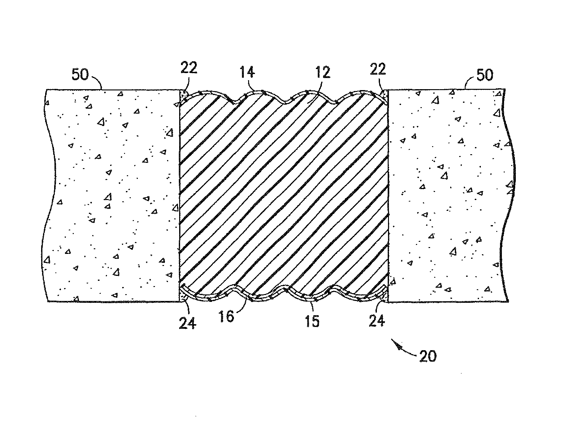
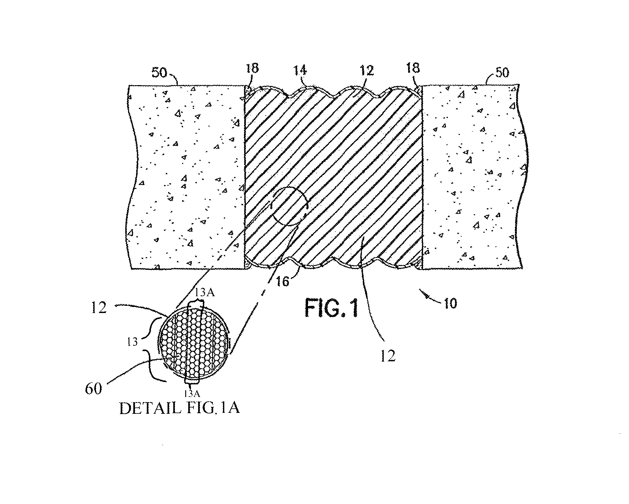
[0023]The expansion joint system described is best understood by referring to the attached drawings. The expansion joint system as described herein is shown as being installed between concrete substrates. The present invention is not limited in this regard, however, as the expansion joint system may be installed between substrates or surfaces other than concrete. Materials for such substrates or surfaces include, but are not limited to, glass, asphalt, stone (granite, marble, etc.), metal, and the like.

[0024]Referring to FIG. 1, one embodiment of an expansion joint system is shown at 10 and is hereinafter referred to as “system 10.” In system 10, compressed laminations 13 of open celled polyurethane foam 12 (hereinafter referred to as “foam 12”) are infused with a fire retardant material 60 (as illustrated in Detail FIG. 1A) to form the defined expansion joint locatable between coplanar concrete substrates 50. As stated above, the present invention is not limited to the use of polyu...


PUM

PropertyMeasurementUnit
temperatureaaaaaaaaaa
densityaaaaaaaaaa
densityaaaaaaaaaa

Abstract

A fire resistant and water resistant expansion joint system comprises a compressed lamination of fire retardant infused open celled foam, one coat of an elastomeric waterproofing or water resistant material on the lamination, and another coat of an intumescent material on an opposing surface of the lamination, thereby providing fire resistance in one direction and water resistance in the opposite direction. The intumescent material may be further coated with a similar elastomeric material, thereby providing fire resistance in one direction and water resistance in both directions. In the alternative, the compressed lamination may comprise first and second opposing layers of intumescent material thereon each having a respective layer of elastomeric material to provide both water resistance and fire resistance in both directions.

Description

CROSS REFERENCE TO RELATED APPLICATION[0001]This application is a Continuation Application of U.S. patent application Ser. No. 12 / 622,574, filed on Nov. 20, 2009, which claims the benefit of U.S. Provisional Patent Application No. 61 / 116,453, filed on Nov. 20, 2008, the contents of each of which are incorporated herein by reference in their entireties and the benefits of each are fully claimed herein.TECHNICAL FIELD[0002]The present invention relates generally to joint systems for use in architectural applications and, more particularly, to an expansion joint system for use in building and construction systems.BACKGROUND[0003]Building and construction applications in which materials such as concrete, metal, and glass are used typically employ joint systems that accommodate thermal and / or seismic movements of the various materials thereof and / or intentional movement of various elements relative to each other. These joint systems may be positioned to extend through both the interior a...

Claims


Application Information

Patent Timeline
Patent Type & Authority Patents(United States)
IPC IPC(8): E04B1/68
CPCE04B1/948E04B1/944E04B1/6806E04C2/205E04B1/6812E04B1/68C08K3/016E04B1/98C08J9/365C08J9/40C08J2201/038C08J2205/05C08J2375/04C08J2400/26E04B1/66
Inventor WITHERSPOON, BILL
Owner EMSEAL JOINT SYST
Why Eureka
Try Eureka