Hydrodynamic bore seal

a technology of hydrodynamic and bore seals, applied in the direction of engine seals, leakage prevention, borehole/well accessories, etc., can solve the problem of convergent leakage path between the finger foot surface and the bor

Inactive Publication Date: 2014-06-03
EXPONENTIAL TECHNOLOGY
View PDF55 Cites 18 Cited by
  • Summary
  • Abstract
  • Description
  • Claims
  • Application Information

AI Technical Summary

Problems solved by technology

This incline causes a convergent leakage path between the finger foot surface and the bore.

Method used


Image

  • Hydrodynamic bore seal
  • Hydrodynamic bore seal
  • Hydrodynamic bore seal

Examples


Embodiment Construction

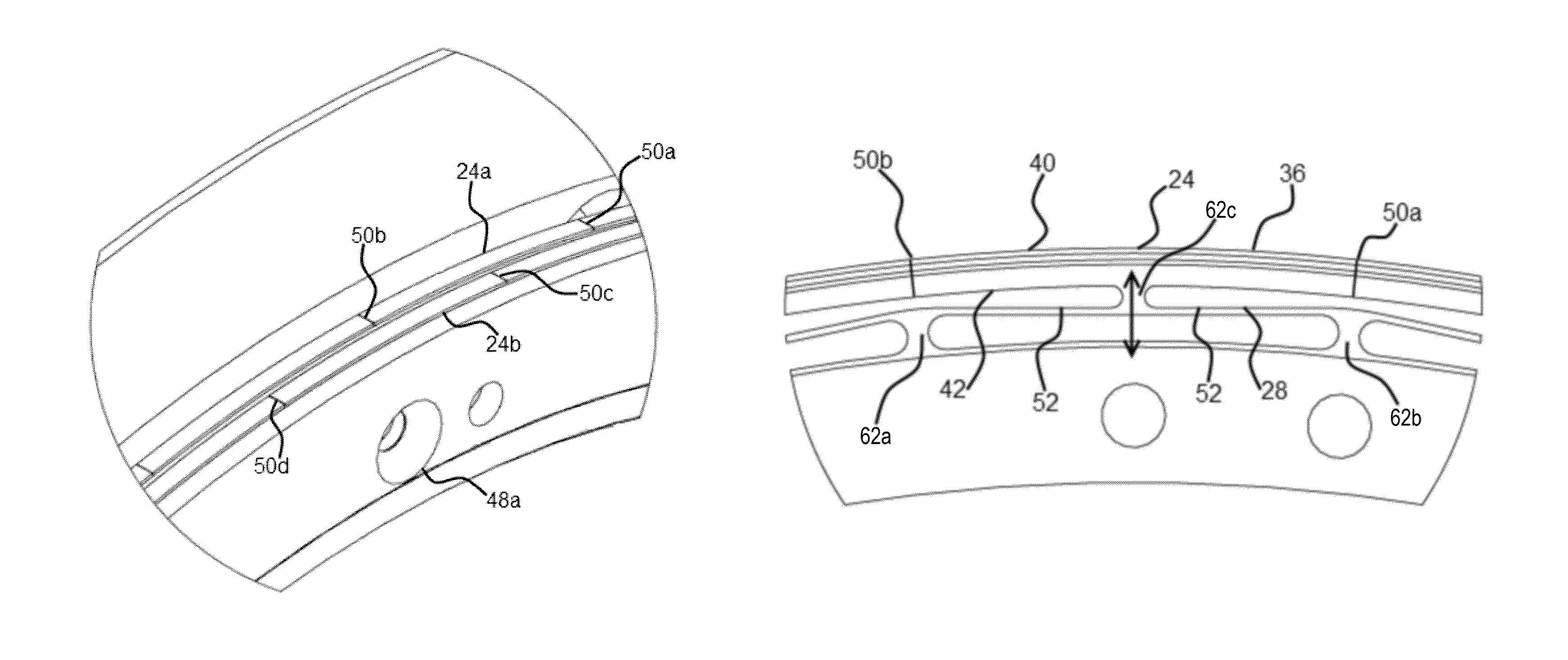
[0029]The attached figures illustrate the design of an improved finger seal 20 and a preferred assembly embodiment. The seal 20, in this embodiment, is configured to seal inside of a bore, however, a similarly designed seal could be designed to seal on a shaft by inverting the features.

[0030]To ease in understanding, an alphanumeric number system will be used comprising numeric references to groups, such as the number 24 regarding a pad, and an alpha suffix referring to particular elements with the group, such as individual pads 24a and 24b.

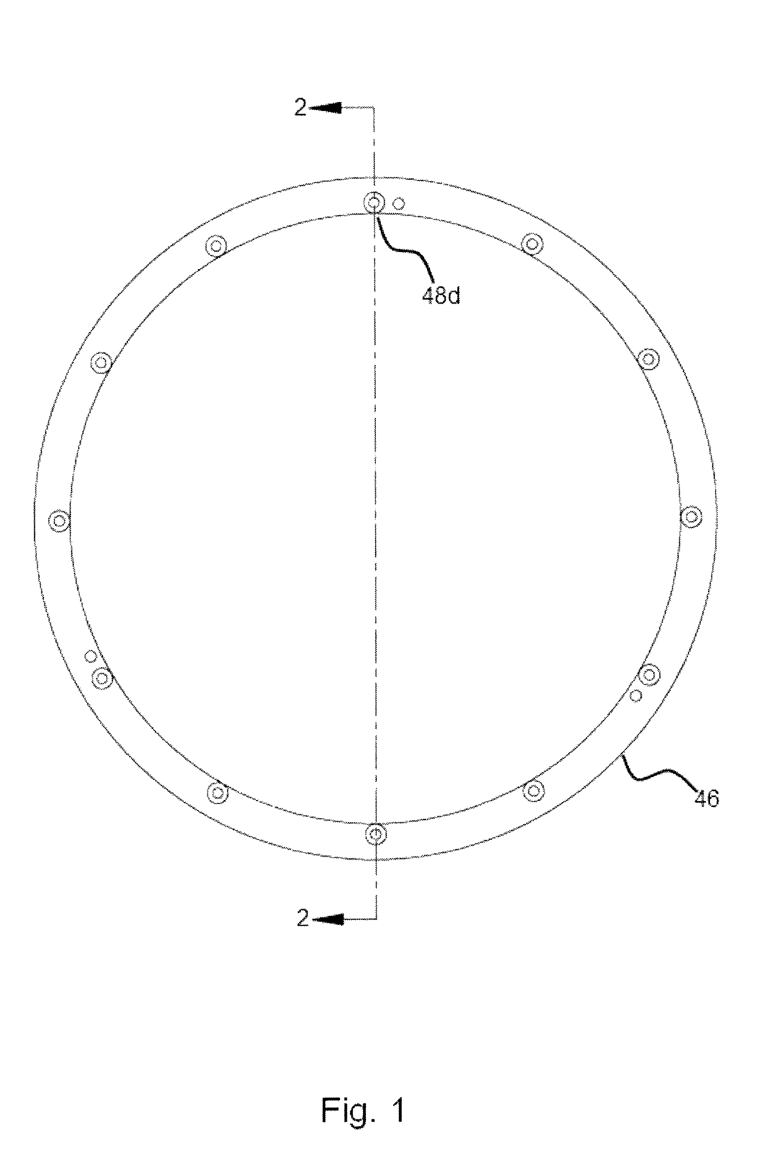
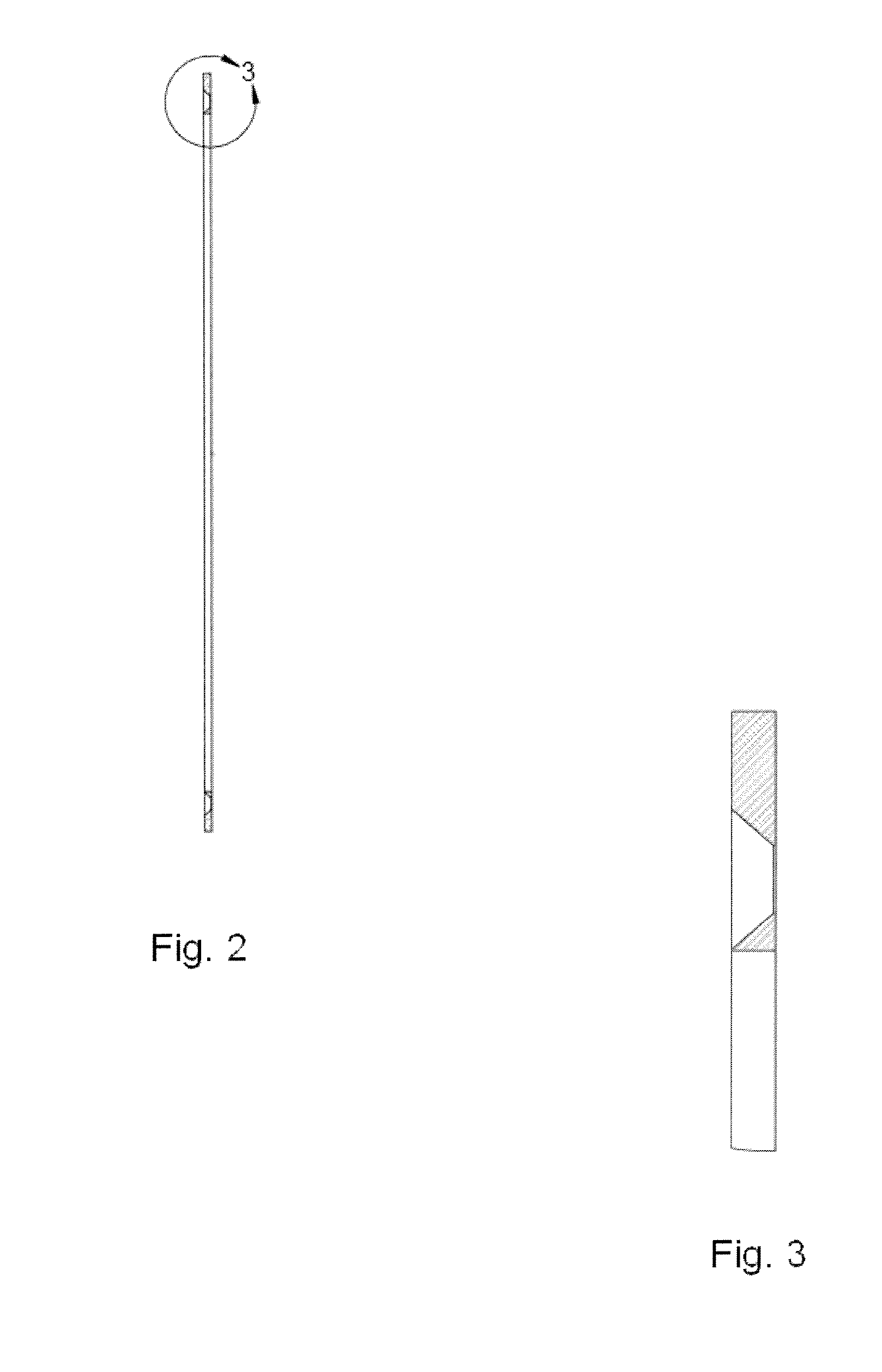
[0031]The seal 20 comprises one or more sealing rings 26, as shown in FIG. 9, that rest up against one or more backing plates (seal holder) 46. Each of the sealing rings 26 is designed to have an “L” shape profile and a taper angle 22 on the sealing diameter 36 (see FIG. 12) of the sealing ring 26. There are a number of “pads”24 on the outside diameter of each sealing ring 26 shown in the figures. The taper angle 24 is provided on the outside di...


PUM


Abstract

The disclosed finger seals are designed to be operational under rotational velocity or a stationary condition. The contact surface of the finger seals is inclined in an axial direction. The rotational velocity of the bore does not affect the hydrodynamic lift and the finger seals can operate at any rotational speed, unlike prior finger seal where the hydrodynamic lift is generated by rotational velocity. Each finger seal is pressure balanced. The pressure chambers on the two sides of each finger seal are connected through the finger cutouts. The finger seal design is such that the fingers lift and move away from the bore surface in radial direction. In one form, each finger seal is designed with the specific required length to allow sufficient surface area for the hydrodynamic force such that the finger seals would be lifted from the bore surface at the design pressure.

Description

RELATED APPLICATIONS[0001]This application claims priority benefit of U.S. Provisional Ser. No. 61 / 183,846, filed Jun. 3, 2009.BACKGROUND OF THE DISCLOSURE[0002]a) Field of the Disclosure[0003]This disclosure relates to the field of hydrodynamic bore seals, and in particular to layered finger seals of a novel design and arrangement.[0004]b) Background Art[0005]Some examples of dry running seals to seal against leakage of a compressed gas include finger seals, brush seals and labyrinth seals. Typically, these seals are used in turbines, or other high-temperature, high-speed applications where lubricated seals or positive seals fail. Some examples of finger seals are described in patents such as US 2008 / 0122183, U.S. Pat. No. 6,196,550, U.S. Pat. No. 5,108,116, and U.S. Pat. No. 6,736,401.[0006]In patent application US 2008 / 0122183 is disclosed hydrodynamic sealing pads comprising one or two taper angles, one taper angle in the direction of shaft speed (tangential) and the other taper...

Claims


Application Information

Patent Timeline
Patent Type & Authority Patents(United States)
IPC IPC(8): F16J15/447
CPCF16J15/441F01D11/02F16J15/54
Inventor PATTERSON, CURTISJUAN, ALEJANDROFARSHCHIAN, SOHEIL
Owner EXPONENTIAL TECHNOLOGY
Why Eureka
Try Eureka