
Method of separating two dispersed-phase immiscible liquids

a technology of immiscible liquid and dispersed phase, which is applied in the direction of gravity filter, loose filtering material filter, stationary filter element filter, etc., can solve the problems of limited efficiency, excessive cost and size, and the inability to take into account coalescence phenomena by using these laws, etc., to achieve fixed separation efficiency, fixed separation efficiency, and fixed separation efficiency

Inactive Publication Date: 2012-05-24
FALAPPI STEFANO +4
View PDF0 Cites 10 Cited by
  • Summary
  • Abstract
  • Description
  • Claims
  • Application Information

AI Technical Summary

Benefits of technology

"The invention relates to a method for separating two liquids that don't mix well. The method involves using a gravity separator and measuring various parameters of the liquids and the separator. These parameters are then used to determine the optimal conditions for separation. The method can be used to separate emulsions of water and oil, and the parameters can include sedimentation time, sizing of the separator, and the flow rate of the liquids. The invention provides a more efficient and effective way to separate liquids that are difficult to separate using conventional methods."

Problems solved by technology

However, using these laws does not allow to take account of coalescence phenomena between water drops and of the presence of a dense emulsion phase at the free water / emulsion interface.
Thus, the separators are either oversized, which results in excessive cost and size, or undersized, which results in limited efficiency.

Method used


Image

  • Method of separating two dispersed-phase immiscible liquids
  • Method of separating two dispersed-phase immiscible liquids
  • Method of separating two dispersed-phase immiscible liquids

Examples


Embodiment Construction

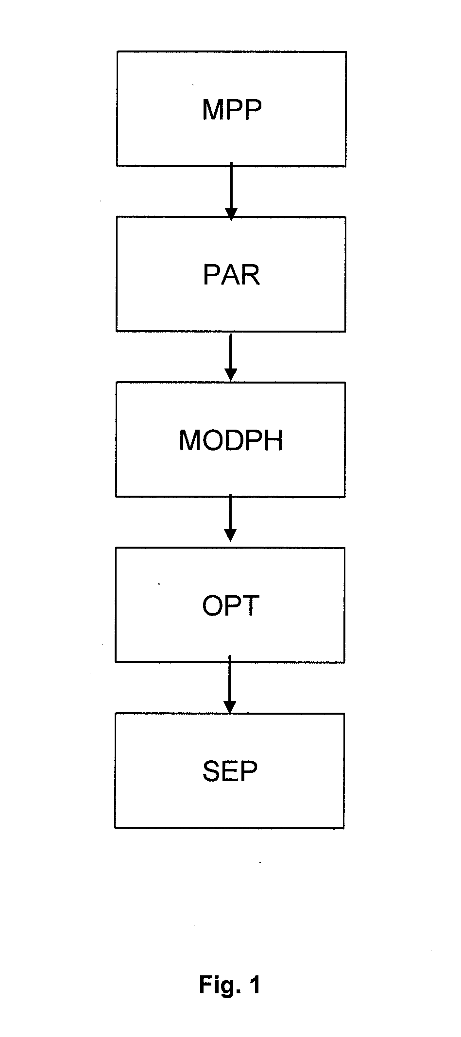
[0045]FIG. 1 shows a flow chart of the alternative method of separating two dispersed-phase immiscible liquids according to the invention.

[0046]The method essentially comprises the following stages:

[0047]1—Measurement of physico-chemical properties relative to the liquids and to the dispersed phase (MPP)

[0048]2—Selection of predetermined parameters linked with the operation and the sizing of the separator (PAR)

[0049]3—Definition of a physical separation model according to the parameters (MODPH)

[0050]4—Using the model for determining all the non-fixed parameters and carrying out separation while respecting the values of the parameters (OPT, SEP).

[0051]The nomenclature used in the description is given in detail in Appendix 1.

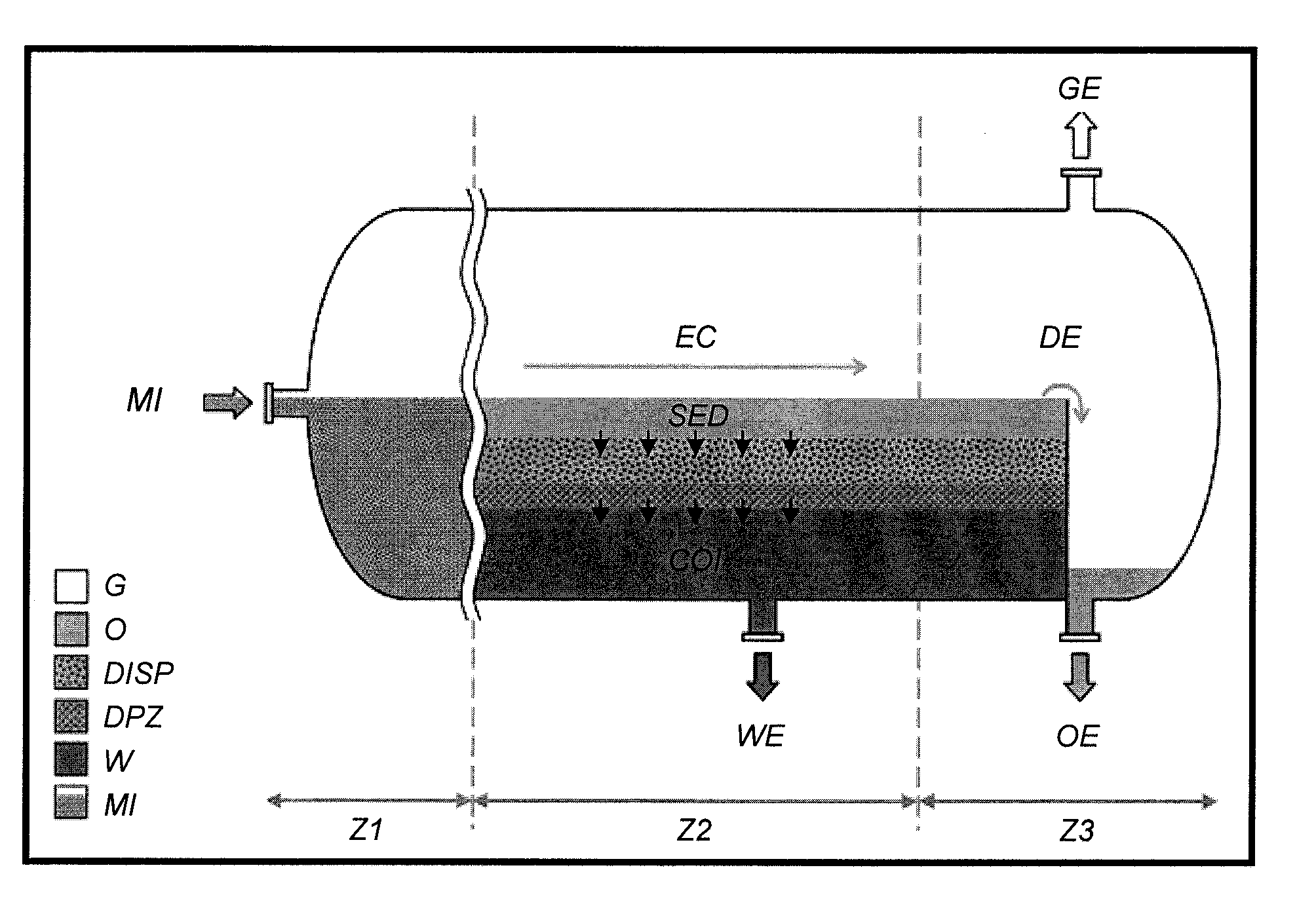
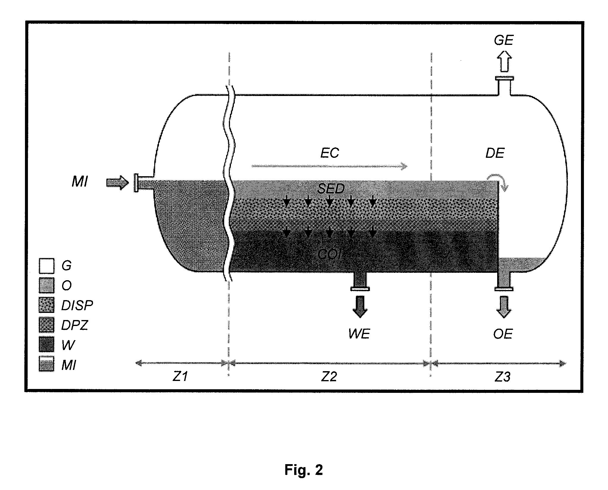
[0052]According to a particular embodiment example, a horizontal gravity separator of cylindrical shape is used to separate an oil and water emulsion.

[0053]1—Measurement of Physico-Chemical Properties Relative to the Liquids and to the Dispersed Phase

[0054]The fol...


PUM

PropertyMeasurementUnit
sizeaaaaaaaaaa
physico-chemical parametersaaaaaaaaaa
physico-chemicalaaaaaaaaaa

Abstract

Method of separating two dispersed-phase immiscible liquids. The two liquids are fed into a gravity separator where both liquids are separated by decantation. A first phase consisting of a first liquid is obtained at the bottom of the separator, a second phase consisting of the second liquid is obtained at the tap of the separator, a third phase containing the two dispersed-phase immiscible liquids and a fourth phase containing the two immiscible liquids in a dense bed are obtained. Physico-chemical properties of the liquids and of the dispersed phase are measured, and a physical separation model is defined. This model is defined considering that the separator works under stationary conditions, using a matter conservation balance for the first fluid within the dense bed, while taking account of a first phenomenon of coalescence between water drops within the third phase, and of a second phenomenon of coalescence between water drops of the fourth phase and the first phase. This model is then used to optimize implementation of the separation. Application to the separation of petroleum effluents for example.

Description

FIELD OF THE INVENTION[0001]The present invention relates to the sphere of treatment of effluents comprising two dispersed-phase immiscible liquids, such as petroleum effluents from production wells.[0002]In particular, the invention relates to a method of separating two immiscible liquids in emulsion, notably water and liquid hydrocarbons.[0003]It is important to separate the water from the liquid hydrocarbons produced so as to increase the quality thereof and to facilitate treatment and transport thereof. Now, after passage of the emulsified effluent through conventional water / hydrocarbon separators, the latter still contains 1 to 5% residual emulsified water in the liquid hydrocarbons.[0004]It is important to decrease the amount of residual water in order to meet the technical specifications of downstream processes.BACKGROUND OF THE INVENTION[0005]There are known techniques allowing to define the dimensions of gravity separators in order to improve separation. In most cases, a me...

Claims


Application Information

Patent Timeline
Patent Type & Authority Applications(United States)
IPC IPC(8): B01D17/025
CPCB01D17/0211B01D17/047B01D17/0214
Inventor FALAPPI, STEFANOPALERMO, THIERRYNOIK, CHRISTINEBROCART, BENJAMINRICORDEAU, ALAIN
Owner FALAPPI STEFANO
Learn More