
Cooling assembly for chilling or freezing liquid ingredients

a technology of liquid ingredients and cooling components, which is applied in the field of cooling assemblies, can solve the problems of affecting the cooling effect of the motor, the possibility of stalling or burning out the motor, and the tedious manual turning and agitation of the canister during the ice cream making process, so as to reduce heat transfer, reduce heat transfer, and reduce the effect of heat transfer

Active Publication Date: 2014-10-30
INDAL REVOLUTION
View PDF18 Cites 11 Cited by
  • Summary
  • Abstract
  • Description
  • Claims
  • Application Information

AI Technical Summary

Benefits of technology

The patent describes a cooling assembly for a container that can hold materials to be cooled. The assembly includes a lid with a movable flap that can be adjusted without affecting the seal between the lid and the outer container. The flap can be positioned in a projecting position to support the cooling assembly in a stationary condition, making it easier to load materials into the inner canister. The flap can also be pivotably mounted on the lid, providing stable positioning of the flap at different rotational orientations. The cooling assembly can be maintained in a stationary condition for loading the inner canister when the flap associated with the lid or the outer container projects. The outer container may have a multi-layer construction with an insulating chamber between the cooling chamber and the ambient exterior environment, reducing heat transfer and facilitating rapid and efficient cooling of the materials. The external elastomeric shell may also have an internal wall that provides structural reinforcement and facilitates mounting of the external and internal shells to one another.

Problems solved by technology

Manual turning and agitation of the canister during the ice cream making process is tedious, and motorized turning systems have been developed.
Drawbacks of motorized systems include the necessity of having a nearby electrical source and the possibility of stalling or burning out the motor as a consequence of the canister jamming in the ice / salt bath or an agitation device jamming in the canister.

Method used


Image

  • Cooling assembly for chilling or freezing liquid ingredients
  • Cooling assembly for chilling or freezing liquid ingredients
  • Cooling assembly for chilling or freezing liquid ingredients

Examples


Embodiment Construction

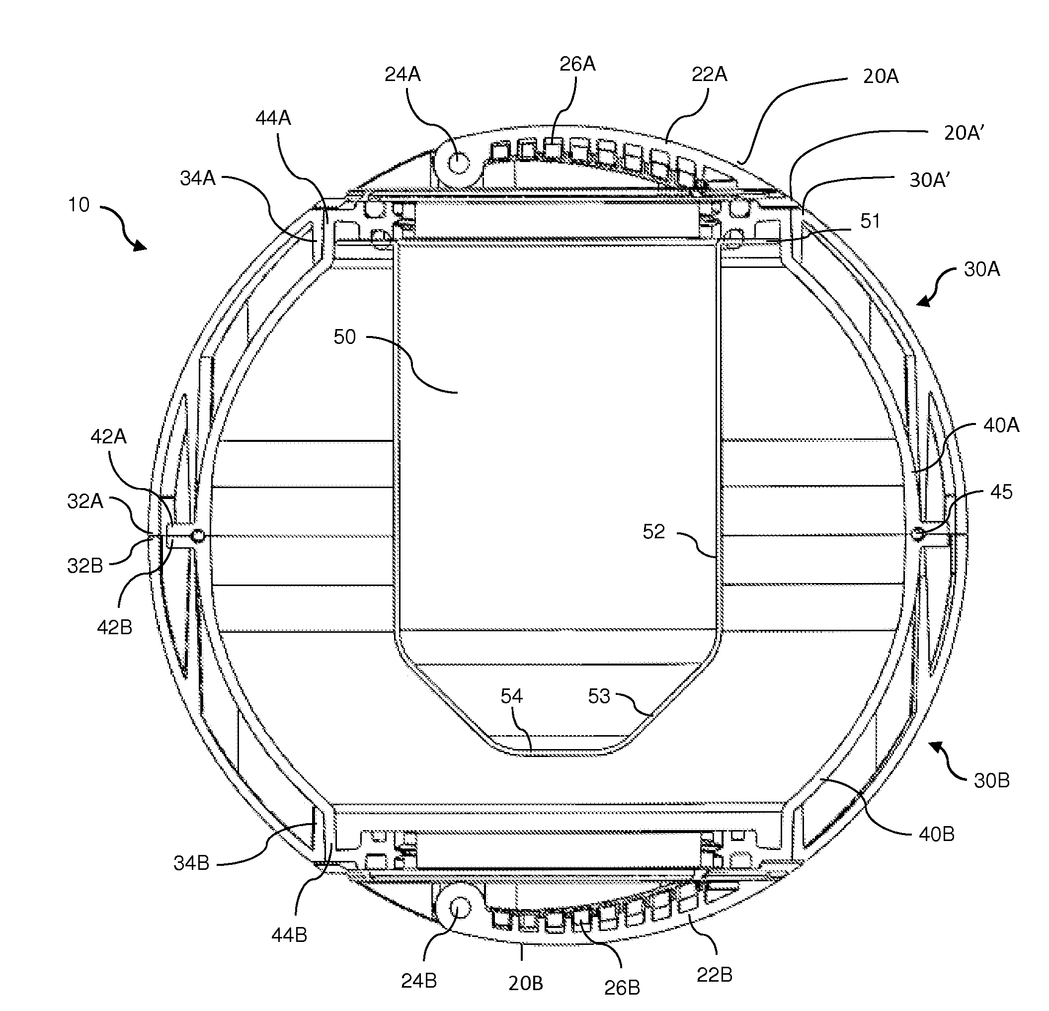
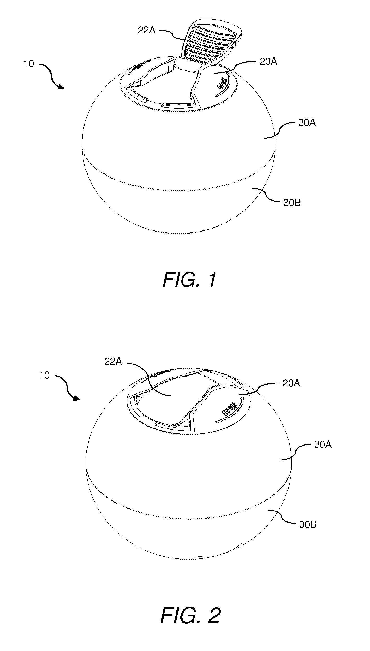
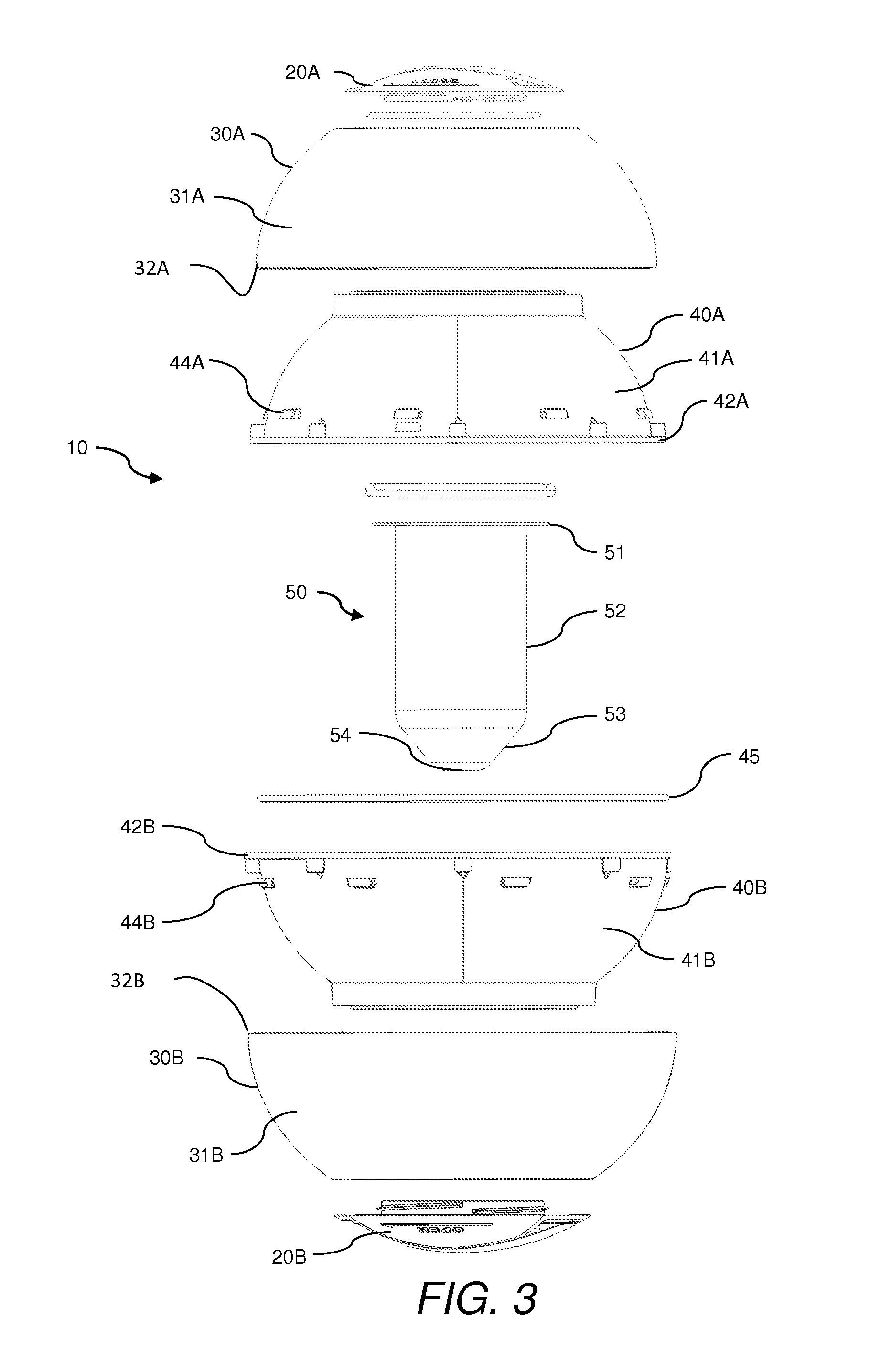
[0024]FIG. 3 illustrates an exploded view of one exemplary construction of a cooling and / or freezing assembly 10 of the present disclosure (referred to herein simply as a “cooling assembly”), and FIG. 4 illustrates a cross-sectional view of an assembled cooling assembly 10. In the exemplary embodiment illustrated, cooling assembly 10 comprises an inner canister lid 20A and a cooling chamber lid 20B; external elastomeric shell components 30A, 30B; rigid internal shell components 40A, 40B; inner canister 50; and sealing members such as gaskets, providing substantially water-tight seals at the interfaces of various components. The external elastomeric shell and internal rigid shell components have partially spherical major surfaces 31A, 31B and 41A, 41B, respectively, and are fabricated as partially hemi-spherical components that can be assembled and, in combination with lids, provide a generally spherical outer container.

[0025]The outer container formed by the combination of lids 20A,...


PUM


Abstract

Cooling assemblies having a sealable cooling chamber formed as the interior volume of a curved or spherical outer container and a sealable inner canister are disclosed. The outer container may be provided as a multi-layer container having an external elastomeric shell. The external elastomeric shell may have an inner framework including a plurality of longitudinal ribs and a reinforcing wall. A movable flap adjustable between a projecting condition in which the flap extends from the exterior surface of the outer container and a closed position in which the flap doesn't project may be provided for supporting the cooling assembly in a stationary condition and the flap may be used as a handle for opening a lid.

Description

CROSS REFERENCE TO RELATED APPLICATION(S)[0001]This application claims the benefit of U.S. provisional patent application Ser. No. 61 / 793,728 (filed Mar. 15, 2013) which is incorporated herein by reference in its entirety.BACKGROUND[0002]1. Technical Field[0003]The following disclosure relates to cooling assemblies having a sealable cooling chamber for cooling liquids or other materials contained in an inner canister and, in particular, relates to cooling assemblies such as ice cream makers having an inner canister for receiving ice cream ingredients and a sealed cavity formed between the inner canister and an outer wall for receiving a chilling substance such as an ice / salt mixture.[0004]2. Related Art[0005]Various types of ice cream and frozen dessert makers are known in the patent literature and many different ice cream makers have been sold commercially. Many ice cream makers have a thermally conductive canister containing the liquid ingredients that mounts in a larger reservoir...

Claims


Application Information

Patent Timeline
Patent Type & Authority Applications(United States)
IPC IPC(8): A23G9/08
CPCA23G9/086A01J9/04A23G9/10B65D25/2858B65D51/249B65D81/18B65D85/78B65D2525/283B65D2525/288F25D3/06F25D3/08F25D5/02F25D2303/083
Inventor ESAREY, GRAEME
Owner INDAL REVOLUTION
Learn More