Automatic transmission system and method for controlling thereby

a transmission system and automatic technology, applied in the direction of multiple ratio transmission, mechanical equipment, transportation and packaging, etc., can solve the problems of difficulty in comprehending an entire individual, inaccurate calculation or estimation of oil pressure characteristic value of friction engagement elements,

Inactive Publication Date: 2005-03-29
AISIN SEIKI KK
View PDF7 Cites 12 Cited by
  • Summary
  • Abstract
  • Description
  • Claims
  • Application Information

AI Technical Summary

Benefits of technology

According to an aspect of the present invention, an automatic transmission system includes an automatic transmission with a driving torque transmitting member, a torque converter with the driving torque transmitting member so as to transmit driving torque from a crankshaft to the automatic transmission in response to rotation of the driving torque transmitting member, plural friction engagement elements housed in the automatic transmission and engaged or disengaged for attaining plural shift stages, and a control unit for controlling an oil pressure to be supplied to the friction engagement elements and for controlling an engaging operation or a disengaging operation of the friction engagement elements based upon the controlled oil pressure supplied to the friction engagement elements, wherein one of the friction engagement elements is disengaged based upon the oil pressure controlled by the control unit, a side of the one of the friction engagement elements is transmitted with the rotation of the driving torque transmitting member, and the other side of the one of the friction engagement elements is locked not to be rotated during a vehicle at a stationary condition. The automatic transmission system further includes a rotational speed detecting means for detecting a variation of a rotation number of the driving torque transmitting member when the one of the friction engagement elements is controlled to be engaged. Therefore, an oil pressure characteristic value of the one of the friction engagement elements is learned by the control unit based upon the variation of the rotation number of the driving torque transmitting member when the one of the friction engagement elements is initially controlled to be engaged.
According to an aspect of the present invention, the oil pressure characteristic value is a pre-charge maximum time determined based upon the variation of the rotation number of the driving torque transmitting member while the oil pressure supplied to the one of the friction engagement elements is maintained at a predetermined oil pressure by the control unit.
According to another aspect of the present invention, the oil pressure characteristic value is a standby pressure determined based upon the variation of the rotation number of the driving torque transmitting member while the oil pressure to be supplied to the one of the friction engagement elements is gradually increased or gradually decreased by a predetermined step pressure every predetermined time by the control unit.
It is preferable that the one of the friction engagement elements is released from being engaged based upon the oil pressure controlled by the control unit when the variation of the rotation number of the driving torque transmitting member reaches a predetermined rotation number.

Problems solved by technology

When the automatic transmission, an engine, an electronic control unit, and the solenoid valve (an oil pressure control unit) have been mounted on a vehicle at a delivery initial condition, it may be difficult to comprehend an entire individual difference so that the oil pressure characteristic value for the friction engagement element may not be accurately calculated or estimated at the start of engagement thereof by the foregoing conventional oil pressure control device.

Method used


Image

  • Automatic transmission system and method for controlling thereby
  • Automatic transmission system and method for controlling thereby
  • Automatic transmission system and method for controlling thereby

Examples


Embodiment Construction

An embodiment of the present invention will be described hereinbelow in detail with reference to the accompanying drawings.

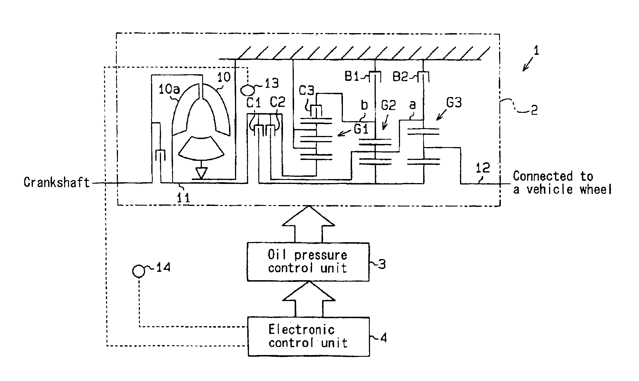
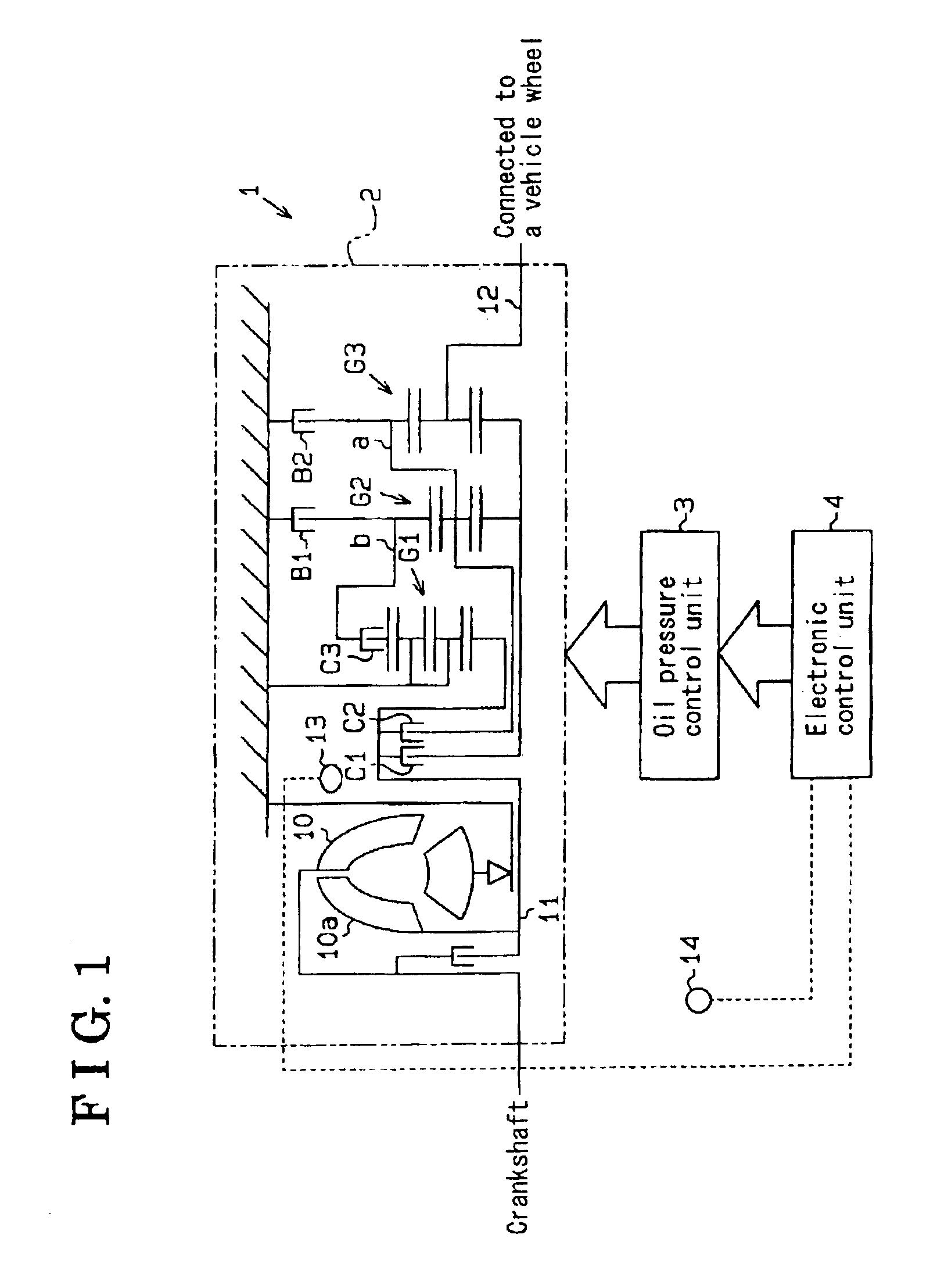
As especially seen in FIG. 1, an automatic transmission system 1 according to the embodiment of the present invention includes an automatic transmission 2, an oil pressure control unit 3, and an electronic control unit 4. The oil pressure control unit 3 and the electronic control unit 4 functions as a control unit.

The automatic transmission 2 is connected to a crankshaft of an engine (not shown) and transmits an engine torque to a vehicle wheel (not shown). The automatic transmission 2 is provided with a torque converter 10, which is connected to the crankshaft, a turbine 10a (i.e. a driving torque transmitting member), which is disposed in the torque converter 10 and is connected to an input shaft 11 of the automatic transmission 2, an output shaft 12, which is connected to the vehicle wheel via a differential gear (not shown), a first single pinion planetary g...


PUM


Abstract

An automatic transmission system for a vehicle includes a rotational speed detector for detecting a variation of a rotation number of driving torque transmitting member when a friction engagement element, which has been disengaged based upon oil pressure controlled by a control unit, a side of which has been transmitted with the rotation of the driving torque transmitting member, and the other side of which is locked not to be rotated during the vehicle at a stationary condition, is controlled to be engaged, wherein an oil pressure characteristic value of the friction engagement element is learned by the control unit based upon the variation of the rotation number of the driving torque transmitting member when the friction engagement element is initially engaged.

Description

CROSS REFERENCE TO RELATED APPLICATIONSThis application is based on and claims priority under 35 U.S.C. §119 with respect to a Japanese Patent Application 2002-091892, filed on Mar. 28, 2002, the entire content of which is incorporated herein by reference.FIELD OF THE INVENTIONThis invention relates to an automatic transmission system. More particularly, relating for determining an oil pressure characteristic value and a method for determining an oil pressure characteristic value by the automatic transmission system.BACKGROUND OF THE INVENTIONAccording to a conventional automatic transmission housing friction engagement elements such as a friction clutch and a friction brake, the friction engagement elements are hydraulically controlled so as to be engaged or disengaged by use of an accumulator and an orifice. However, somewhat recent developments have led to an automatic transmission in which an oil pressure from an oil pressure source is directly controlled by use of a solenoid va...

Claims


Application Information

Patent Timeline
Patent Type & Authority Patents(United States)
IPC IPC(8): F16H61/06F16H61/686F16H61/04
CPCF16H61/061F16H61/686F16H2200/2097F16H2342/042Y10T477/6939F16H2342/04Y10T477/638Y10T477/6895F16H2061/064
Inventor TAKAGI, KIYOHARUSHIMEI, MASATO
Owner AISIN SEIKI KK
Why Eureka
Try Eureka