Low-aspect antenna having a vertical electric dipole field pattern

a vertical electric dipole field and low-aspect antenna technology, applied in the field of antennas, can solve the problems of reducing the antenna aspect, reducing the antenna performance, and reducing the heigh

Active Publication Date: 2014-06-03
LGS INNOVATIONS
View PDF4 Cites 6 Cited by
  • Summary
  • Abstract
  • Description
  • Claims
  • Application Information

AI Technical Summary

Problems solved by technology

However, reducing the antenna aspect may also entail reducing the performance of the antenna.
Reducing the height will typically reduce the bandwidth and / or the efficiency of the antenna.

Method used


Image

  • Low-aspect antenna having a vertical electric dipole field pattern
  • Low-aspect antenna having a vertical electric dipole field pattern
  • Low-aspect antenna having a vertical electric dipole field pattern

Examples


Embodiment Construction

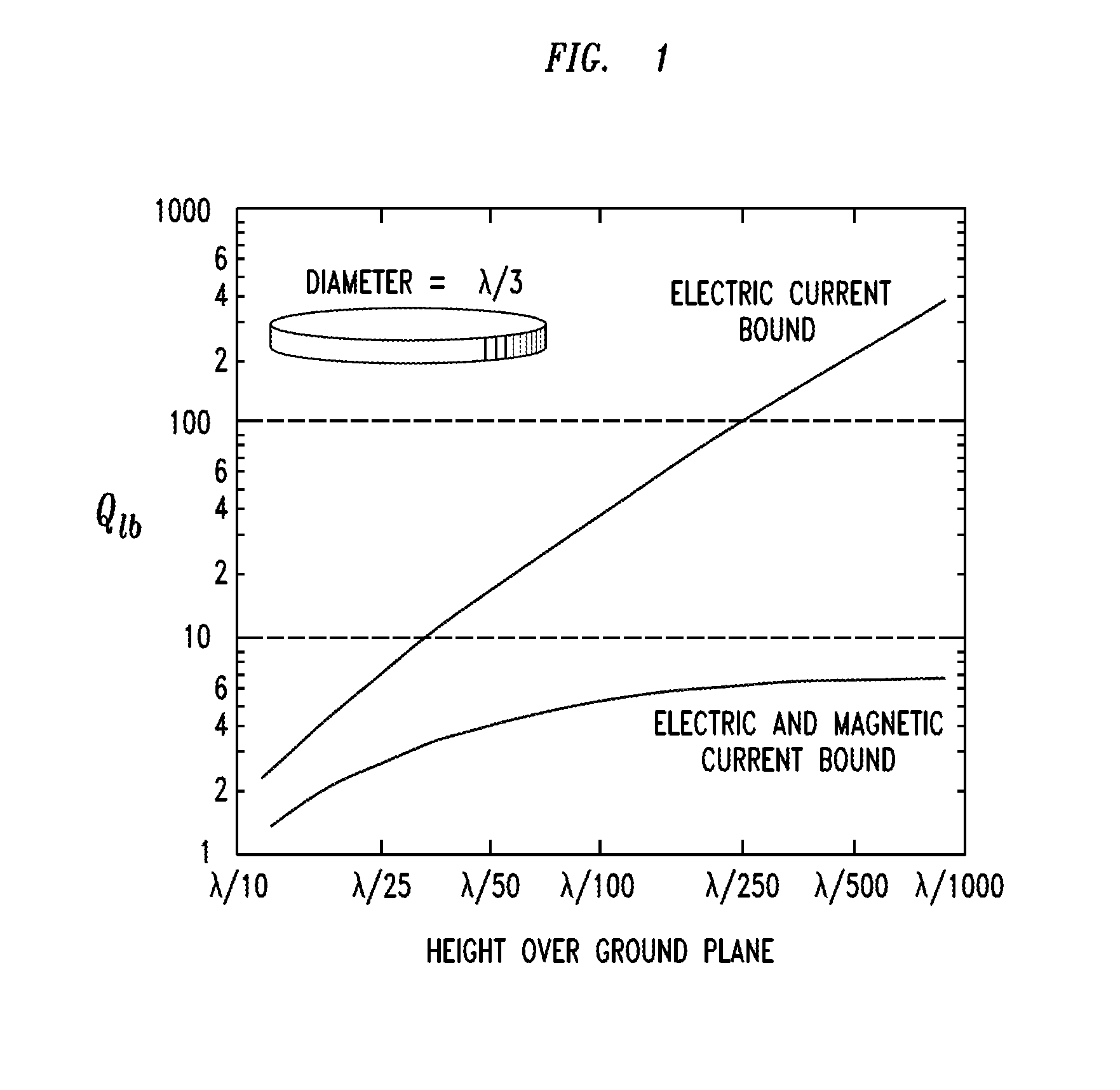
[0018]As noted above, performance limitations become significant as the height of a vertically polarized antenna height is reduced. One illustration of this effect is provided by the simple example of a vertically polarized monopole antenna mounted on a ground plane. It is well known that such an antenna performs well when its length is near λ / 4, λ being the operating wavelength. (Unless stated otherwise, all references to “wavelength” will mean the vacuum wavelength corresponding to a particular RF frequency.) By adding an inductive load near its base, the antenna can be made as short as λ / 20. However, if the antenna is made substantially shorter, its efficiency will be significantly degraded.

[0019]The monopole antenna can also be shortened by covering it with an electrically conductive cap, which may e.g. have the form of a circular disk. Such a configuration is referred to as a “top-loaded monopole”. Top-loaded monopoles have been demonstrated with a height of λ / 12 and an impedan...


PUM


Abstract

An antenna comprises a ring-shaped radiofrequency resonator that defines a path for a circulating magnetic current. In an implementation, the resonator has a height of no more than 2% of an operating wavelength, and it has an electromagnetic resonance at the operating frequency. In an implementation, the antenna is of a type having a vertical, short electric dipole radiation or sensitivity pattern. It comprises, as the dominant radiative element, a ring of material disposed transverse to the vertical dipole axis and having an average magnetic permeability more than ten times the magnetic permeability of air. The ring has a maximum outer diameter and a height that is less than the maximum outer diameter. The antenna further includes a feed structure adapted to couple radiofrequency energy into and / or out of a magnetic current circulating in the ring.

Description

FIELD OF THE INVENTION[0001]The invention relates to antennas, and more particularly to antennas suitable for use in communications at microwave frequencies.ART BACKGROUND[0002]Antennas are often mounted on the external surfaces of ground vehicles and aircraft. In such situations, it is often desirable for the antenna structure to have the lowest aspect possible. By “aspect” is meant the ratio of height, i.e. extent perpendicular to the mounting surface, to lateral extent, i.e., extent parallel to the mounting surface. For example, a small aspect may be desirable to minimize aerodynamic drag, to reduce visual signature, to improve aesthetic appearance, or for other reasons. In some cases, it may be desirable to conform the antenna to the shape of the mounting surface. The smaller the aspect, the more completely such a goal may be achieved.[0003]However, reducing the antenna aspect may also entail reducing the performance of the antenna. For example, many applications require an ante...

Claims


Application Information

Patent Timeline
Patent Type & Authority Patents(United States)
IPC IPC(8): H01Q7/08
CPCH01Q9/36
Inventor STUART, HOWARD, R.
Owner LGS INNOVATIONS
Why Eureka
Try Eureka