
Thermoanalytical instrument

a technology of analytic instruments and instruments, applied in the field of thermoanalytic instruments, can solve the problems of reducing the operational temperature range of the instrument, false or incomplete, waste of precious sample materials, time-consuming,

Active Publication Date: 2014-06-10
METTLER TOLEDO GMBH
View PDF25 Cites 5 Cited by
  • Summary
  • Abstract
  • Description
  • Claims
  • Application Information

AI Technical Summary

Benefits of technology

[0019]The controller dynamically controls either the first compensation heater or the second compensation heater in order to compensate for a temperature difference or differential temperature arising between the first and the second measurement position. The separation of the heater functions by applying the temperature program through the first and second heaters and the additional power through one of the compensation heaters is advantageous to improve the signal-to-noise ratio. The additional or compensation power can be alternatively supplied to either of the measurement positions, depending on which position is cooler and therefore has the highest momentary power demand. The compensation power will always be supplied as a non-negative power value, in particular as a non-negative compensation voltage, which is transformed into a compensation power and further into a compensation temperature.
[0023]Depending on the setup, the controller can either be analog or digital. An analog controller preferably comprises a PID controller for each control loop. A digital controller allows a more flexible approach and can for instance be designed as a fuzzy control system.
[0027]Depending on the quantity of measurements to be run on a single sample material or the quantity of experiments to be performed under similar conditions, it can be advantageous to provide an instrument with multiple pairs of first and second measurement positions, wherein the measurement positions can be arranged on a common holder or on individual holders comprising one or more measurement positions.
[0044]Preferably, each compensation heater is fed an equal offset voltage value. For unequal values the offset temperature depends on the higher offset voltage, while the zero-crossing problem depends on the lower offset voltage. Both effects will decrease the accuracy of the measuring results.
[0049]The detuning of the time constants of the two control loops has the advantage that interference-induced oscillation problems can be avoided as only one control loop acts on a specific measurement position at any time.
[0050]Besides detuning the time constants, switching means can be included into the first and second control loop, which cause the temperature inputted into the first control loop to switch from the first temperature to the second temperature, when the second control loop switches from activating the second compensation heater to activating the first compensation heater and vice versa. Activation is understood in this context as allowing a compensation current to flow to the activated compensation heater. The switching of the input temperature can be linked to the switching of the second control loop. Through this measure it can be prevented that the first and the second control loop are simultaneously active on the same measurement position, whereby the aforementioned possibility of interference between the first and second control loop can be avoided.

Problems solved by technology

Depending on the setup, these drawbacks relate for example to the limited negative compensation headroom, the offset temperature as well as a baseline offset, drift and curvature.
Limited negative compensation headroom can lead to a cutoff of the measurable heat flow and can result in false or incomplete results.
For an unknown sample it might even take several experimental runs to determine the appropriate reference offset power, which can result in wasting precious sample material as well as being time consuming.
Said reference offset power generates an offset temperature, which reduces the operational temperature range of the instrument.
By reducing the reference offset power the offset temperature can also be reduced in order to expand the operational temperature range, but unfortunately this will increase the problem related to the limited negative compensation headroom.
This effect can result in an unwanted baseline drift and / or baseline curvature, which can further be superimposed by intrinsic physical differences between the sample and reference positions.
Controlling a thermoanalytical instrument with the dynamic compensation gives rise to further challenges which will be described in more detail below.
In that event, artifacts caused by the switching can result in inaccurate data and finally in inaccurate experimental results.
Another challenge when providing a thermoanalytical instrument comprising a first and a second compensation heater is to prevent the sensitivity of the second control loop from dropping to zero close to zero-crossings.
The addition of the square root circuit to an analog control loop is a less preferred solution, as it can constitute a possible source of added noise and instability.
Both effects will decrease the accuracy of the measuring results.
A further challenge when implementing the dynamic compensation principle can be the occurrence of asymmetries, especially in a generally symmetrically operated thermoanalytical instrument comprising a first and a second compensation heater.
Unfortunately, the compensation power of the second compensation heater has a direct influence on the temperature of the second measurement position, also referred to as reference position, especially when said second measurement position also receives the compensation power.
This influences the first control loop, which is responsible for imposing the temperature program on the first and second measurement position, and can give rise to interference induced oscillation problems.

Method used


Image

  • Thermoanalytical instrument
  • Thermoanalytical instrument
  • Thermoanalytical instrument

Examples


Embodiment Construction

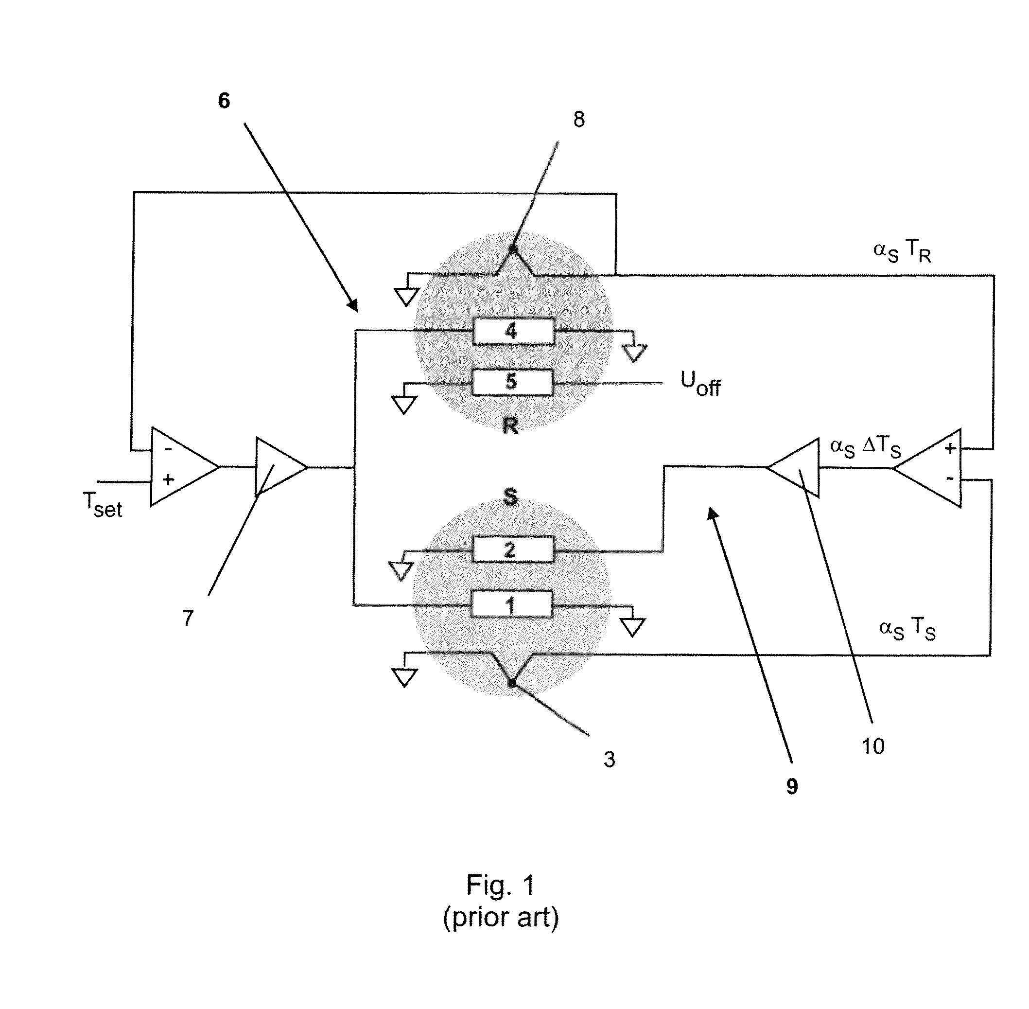
[0071]FIG. 1 shows an electronic setup for a DSC with power compensation, as known in the prior art. The DSC comprises at least two measurement positions, a first measurement or sample position S and a second measurement or reference position R. A sample or sample material can be placed on the sample position S and a reference material can be placed on the reference position R. Experiments on a sample can be performed with and without a reference material.

[0072]The sample position S is in thermal contact with a sample heater 1 and a first compensation heater 2. The temperature at the sample position S is determined by a sensor comprising at least one thermocouple 3. Likewise the reference position R is in thermal contact with a reference heater 4 and a second compensation heater 5, which supplies an offset power arising from a constant offset voltage Uoff. The temperature at the reference position R is determined with a sensor comprising at least one thermocouple 8. The heaters 1, 2...


PUM

PropertyMeasurementUnit
resistanceaaaaaaaaaa
thermal resistanceaaaaaaaaaa
poweraaaaaaaaaa

Abstract

A thermoanalytical instrument, and especially a differential scanning calorimeter, has first and second measurement positions, a heater and a temperature sensor associated with each of the measurement positions, and a controller. The controller, which has an associated means for setting a predetermined temperature program, controls a heating power of the first heater to cause the temperature measured at the first position to follow the temperature program. The controller also controls both heaters to eliminate any temperature difference between the measured first and second temperatures. The controller also provides a means for determining the lower of the measured first and second measured temperatures and applies additional power to the heater associated with that lower measured temperature.

Description

CROSS-REFERENCE TO RELATED APPLICATIONS[0001]This application claims a right of priority under 35 USC §119 from European patent application 08 15 8196.9, filed 13 Jun. 2008, the content of which is incorporated by reference as if fully recited herein.TECHNICAL FIELD[0002]The present invention relates to a thermoanalytical instrument, in particular a differential scanning calorimeter, and to a method for operating such an instrument.BACKGROUND OF THE ART[0003]Thermoanalytical instruments, such as differential scanning calorimeters (DSC), are used to measure different characteristics and properties of a sample which is exposed to a temperature program.[0004]A DSC is utilized to record temperature-related changes of the physical or chemical characteristics of a sample. These are for example heat measurements related to exothermic or endothermic events accompanying transitions and other effects occurring in a sample which is subjected to temperature changes. The changes of the sample ar...

Claims


Application Information

Patent Timeline
Patent Type & Authority Patents(United States)
IPC IPC(8): G01N25/20G01K17/00
CPCG01N25/20G01N25/4866G01K17/04
Inventor VAN DE KERKHOF, ERNSTVAN GRINSVEN, PAUL PIETER WILLEM
Owner METTLER TOLEDO GMBH
Learn More