Planetary gear system and gear reducer

a technology gear reducer, which is applied in the direction of machine/engine, gear, transportation and packaging, etc., to achieve the effect of reducing the agitation resistance of lubricating oil and reducing the power loss of planetary gear system or gear reducer

Active Publication Date: 2014-06-10
KAWASAKI HEAVY IND LTD
View PDF11 Cites 24 Cited by
  • Summary
  • Abstract
  • Description
  • Claims
  • Application Information

AI Technical Summary

Benefits of technology

[0013]Thus, according to the present invention, the agitation resistance of the lubricating oil is reduced, and power loss of the planetary gear system or gear reducer is reduced.

Problems solved by technology

In recent years, one of the key issues in the aircraft industry is to improve the fuel efficiency of aircrafts from the viewpoint of reduction of aircraft operation costs as well as environmental conservation.

Method used


Image

  • Planetary gear system and gear reducer
  • Planetary gear system and gear reducer
  • Planetary gear system and gear reducer

Examples


Embodiment Construction

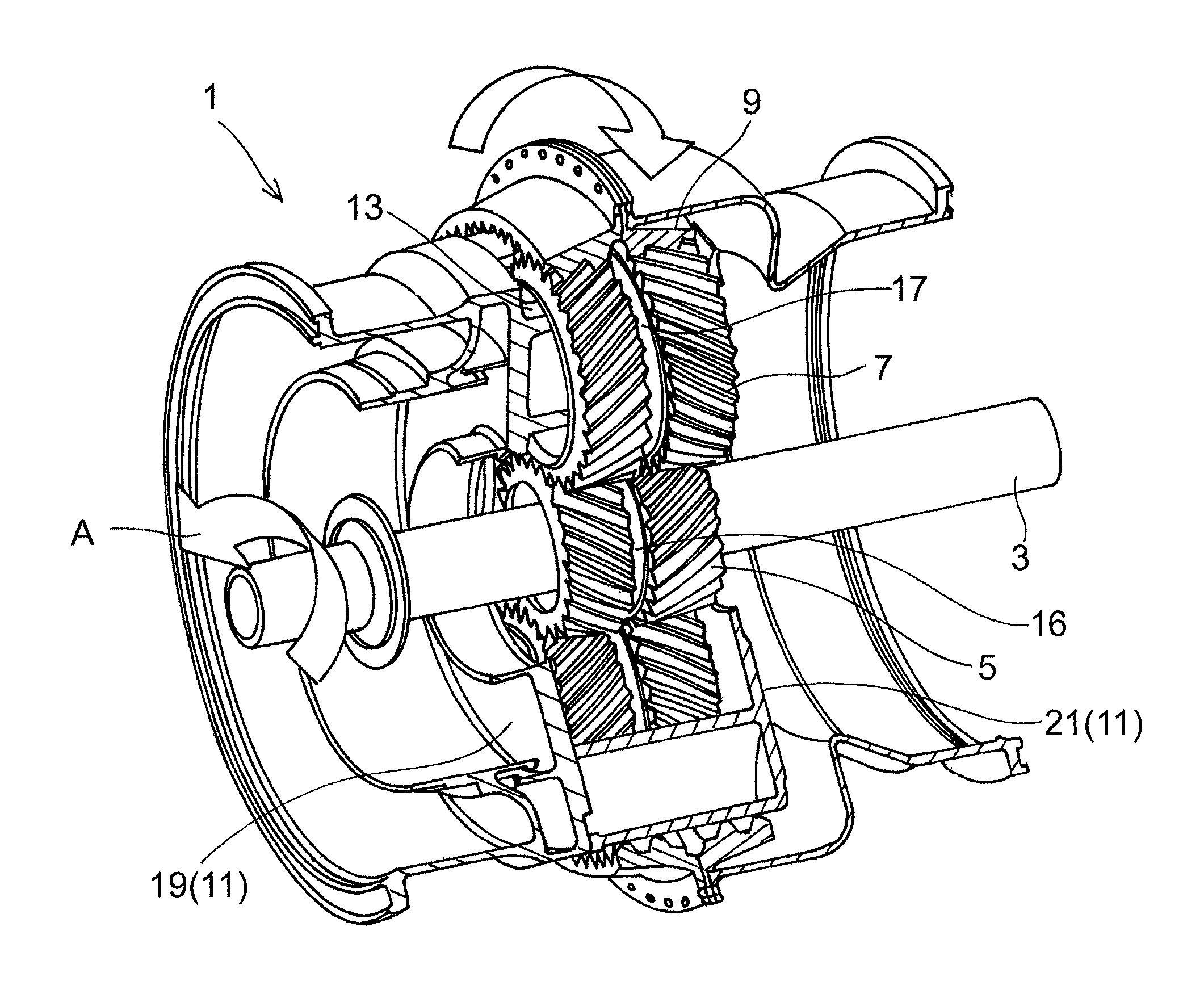
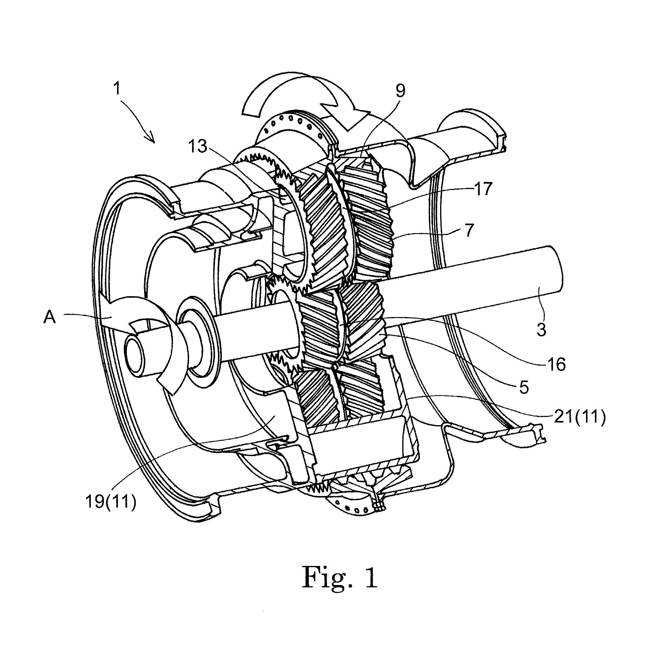
[0023]Hereinafter, a preferred embodiment of the present invention is described with reference to the accompanying drawings. FIG. 1 is a perspective view showing a planetary gear system 1 according to one embodiment of the present invention. The planetary gear system (gear reducer) 1 is installed in an aircraft engine, and transmits power of an input shaft 3 as two outputs. It should be noted that in the description below, along the axial direction of the planetary gear system 1, one side of the planetary gear system 1, at which side the engine is disposed (i.e., the lower left side in FIG. 1), is referred to as a front side, and the opposite side is referred to as a rear side.

[0024]The planetary gear system 1 is configured as a double-row gear mechanism, which includes: a central sun gear 5; planet gears 7; and an outer ring gear 9. The sun gear 5 is a double helical gear including a pair of helical gears and having sets of external teeth, the sets of external teeth being inclined ...


PUM


Abstract

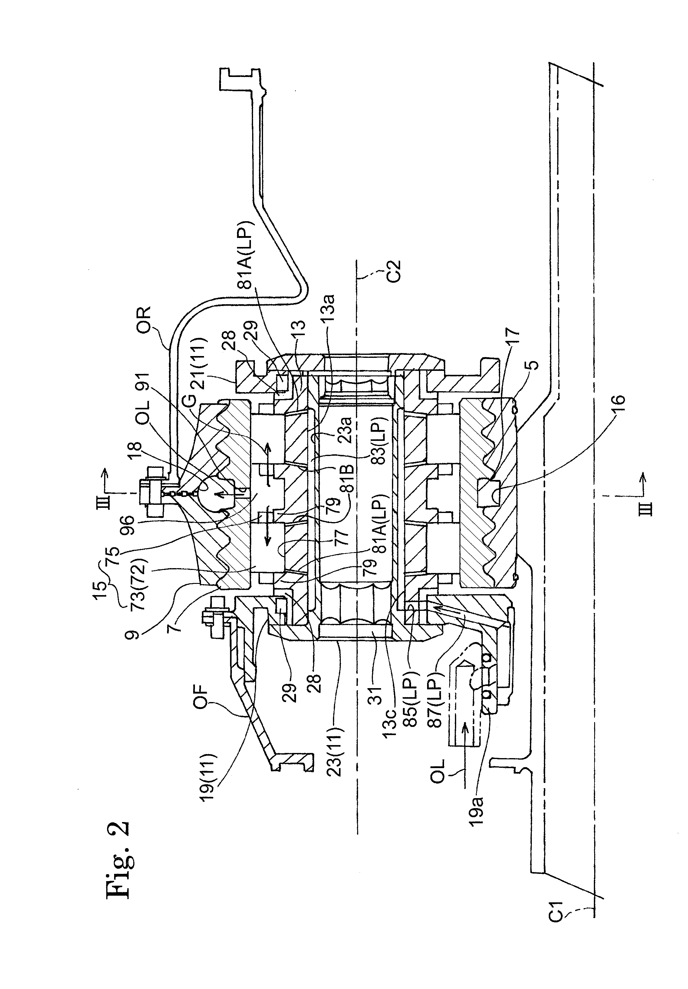
A planetary gear system (1) includes: a sun gear (5) having external teeth; a ring gear (9) having internal teeth; at least one planet gear (7) having external teeth meshed with the external teeth of the sun gear and the internal teeth of the ring gear. The planet gear (7) has, at its outer circumferential face, the external teeth which are formed of a pair of sets of teeth aligned in an axial direction and an annular groove (17) which is formed between the pair of sets of teeth. The planetary gear system (1) further includes: a fixed support shaft (23) provided for each of the at least one planet gear (7) and configured to rotatably support the planet gear (7) via a bearing, the bearing including a pair of rolling element rows (72) aligned in the axial direction; an oil supply path (LP) through which lubricating oil is supplied, at an inner side of the planet gear (7), to the pair of rolling element rows (72); and an oil discharge path (oil outlet 91) which extends through the planet gear (7) and through which the lubricating oil is discharged to the annular groove (17) from space between the pair of rolling element rows (72) which are provided at the inner side of the planet gear (7).

Description

CROSS REFERENCE TO RELATED APPLICATIONS[0001]This application is a National Stage of International Application No. PCT / JP2011 / 002185 filed Apr. 13, 2011, claiming priority based on Japanese Patent Application No. 2010-092560 filed Apr. 13, 2010, the contents of all of which are incorporated herein by reference in their entirety.TECHNICAL FIELD[0002]The present invention relates to a lubricating structure of a gear reducer such as a planetary gear system for use in a power transmission mechanism of an aircraft.BACKGROUND ART[0003]In recent years, one of the key issues in the aircraft industry is to improve the fuel efficiency of aircrafts from the viewpoint of reduction of aircraft operation costs as well as environmental conservation. Accordingly, reduction in power loss of planetary gear systems for use in aircraft engines is also required.[0004]Conventionally, in such a planetary gear system, a double helical gear which includes a pair of helical gears aligned in the axial directi...

Claims


Application Information

Patent Timeline
Patent Type & Authority Patents(United States)
IPC IPC(8): F16H57/04F16H1/28
CPCF05D2260/40311B60K17/046F16H1/28B60Y2200/51F16H57/0486F16H57/0479F02C3/107B64C25/405Y02T50/823F16H57/043F02C7/36F16H57/0409Y02T50/80
Inventor IMAI, HIDEYUKIGOI, TATSUHIKOARISAWA, HIDENORINISHIMURA, MOTOHIKOSATO, MAIKO
Owner KAWASAKI HEAVY IND LTD
Why Eureka
Try Eureka