Racetrack memory with low-power write

a low-power write and memory technology, applied in the field of memory devices, can solve the problems of insulating tunnel barrier breakdown, relatively large current,

Inactive Publication Date: 2014-06-10
IBM CORP
View PDF30 Cites 4 Cited by
  • Summary
  • Abstract
  • Description
  • Claims
  • Application Information

AI Technical Summary

Problems solved by technology

This method of injection uses large currents to generate the necessary magnetic field, which necessitates the use of large amounts of power and large on-chip transistors.
This method also uses relatively large currents and is furthermore susceptible to breakdown of the insulating tunnel barrier between the magnetic nanowire and the ferromagnetic conductor.

Method used


Image

  • Racetrack memory with low-power write
  • Racetrack memory with low-power write
  • Racetrack memory with low-power write

Examples


Embodiment Construction

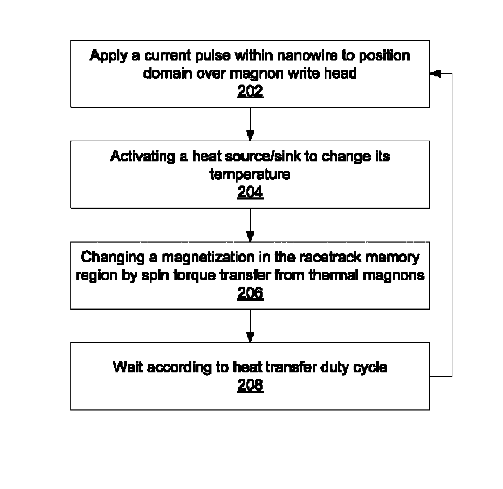
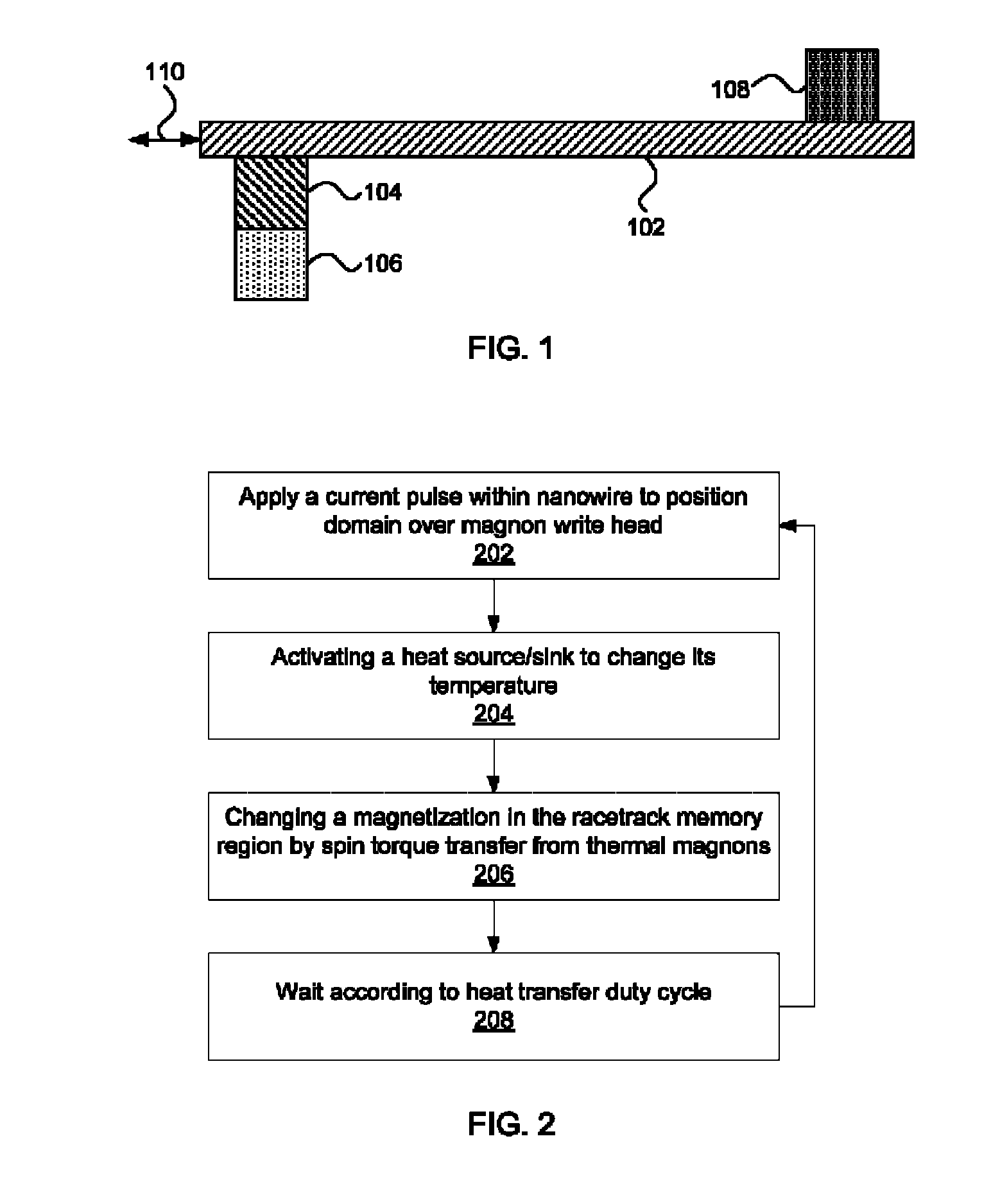
[0020]The present principles provide the ability to write to racetrack memory using a low-power heat source or heat sink to generate magnons. The magnons propagate to the racetrack memory, causing a magnetization change, thereby injecting a domain wall.

[0021]Addressing the physics behind this phenomenon first, the transfer of spin momentum driven by electric current, flowing either through a tunnel barrier or a metallic spacer, creates pseudotorques on the macroscopic spin moments of magnetic electrodes. Thermal effects can be used to transfer spin momentum from a thermally generated magnon concentration existing within an electrically insulating ferromagnet or ferrimagnet, through a normal metal, and into a free magnet. These thermal magnons are an alternative to conventional spin transportation by conducting electrons in a magnetic material.

[0022]One property of magnons is that, unlike electrons, they may be created and annihilated at an interface with a metal, along with a transf...


PUM


Abstract

Methods for writing include applying a current pulse to a racetrack memory medium to position a domain in proximity to a thermally triggered magnon source in contact with the racetrack memory medium; activating a heat source / sink in contact with the magnon source to create a thermal gradient in the magnon source, generating a magnon flow in the magnon source; and changing a magnetization in the racetrack memory medium by spin torque transfer from the magnon flow.

Description

RELATED APPLICATION INFORMATION[0001]This application is a Continuation application of co-pending U.S. patent application Ser. No. 13 / 734,642 filed on Jan. 4, 2013, incorporated herein by reference in its entirety.BACKGROUND[0002]1. Technical Field[0003]The present invention relates to memory devices and, more particularly, to writing magnetic domains to racetrack memory using heating or cooling to generate magnons.[0004]2. Description of the Related Art[0005]Racetrack memory offers high storage densities and high read / write performance by encoding data in walls between magnetic domains along a nanowire. Stored domains are pushed through the memory using a spin-coherent electric current, which moves all domain walls in a consistent direction, regardless of the direction of its particular magnetization.[0006]The injection of domain walls into a magnetic nanowire at specific locations conventionally is accomplished using magnetic fields applied by adjacent current-carrying wires. Such...

Claims


Application Information

Patent Timeline
Patent Type & Authority Patents(United States)
IPC IPC(8): G11C11/14G11C19/08G11C11/00G11C19/00G11C11/15
CPCG11C11/15G11C19/08G11C11/14G11C11/00G11C19/00G11C11/1675G11C19/0858G11C19/0808G11C19/0841
Inventor ABRAHAM, DAVID W.ANNUNZIATA, ANTHONY J.
Owner IBM CORP
Why Eureka
Try Eureka