
Configuration of bus transceiver

a transceiver and bus technology, applied in the field of transceivers, can solve the problems of incompatibility of devices with earlier devices, and the inability to provide a new transceiver as a drop-in replacement for known transceivers, and achieve the effect of improving system reliability

Active Publication Date: 2014-06-10
NXP BV
View PDF10 Cites 14 Cited by
  • Summary
  • Abstract
  • Description
  • Claims
  • Application Information

AI Technical Summary

Benefits of technology

The patent text describes a method for configuring a transceiver based on signals received at the device-side of the transceiver. By doing this, the transceiver can be more robust and accurate in its configuration. The method also allows for different operating modes to be achieved using a transceiver with the same pin layout as existing transceivers. Additionally, the feedback provided by the method helps avoid un-configuration or false configuration of the transceiver, which can lead to system dead-lock or permanent wrong and unwanted wake-ups of the transceiver.

Problems solved by technology

However, in addition to the fact that these examples may provide a more expensive device, the device also is likely to be incompatible with earlier devices.
This means that such a new transceiver may not be provided as a drop-in replacement for known transceivers.

Method used


Image

  • Configuration of bus transceiver
  • Configuration of bus transceiver
  • Configuration of bus transceiver

Examples


Embodiment Construction

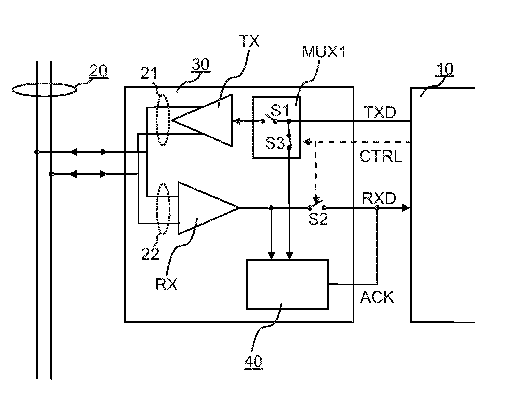
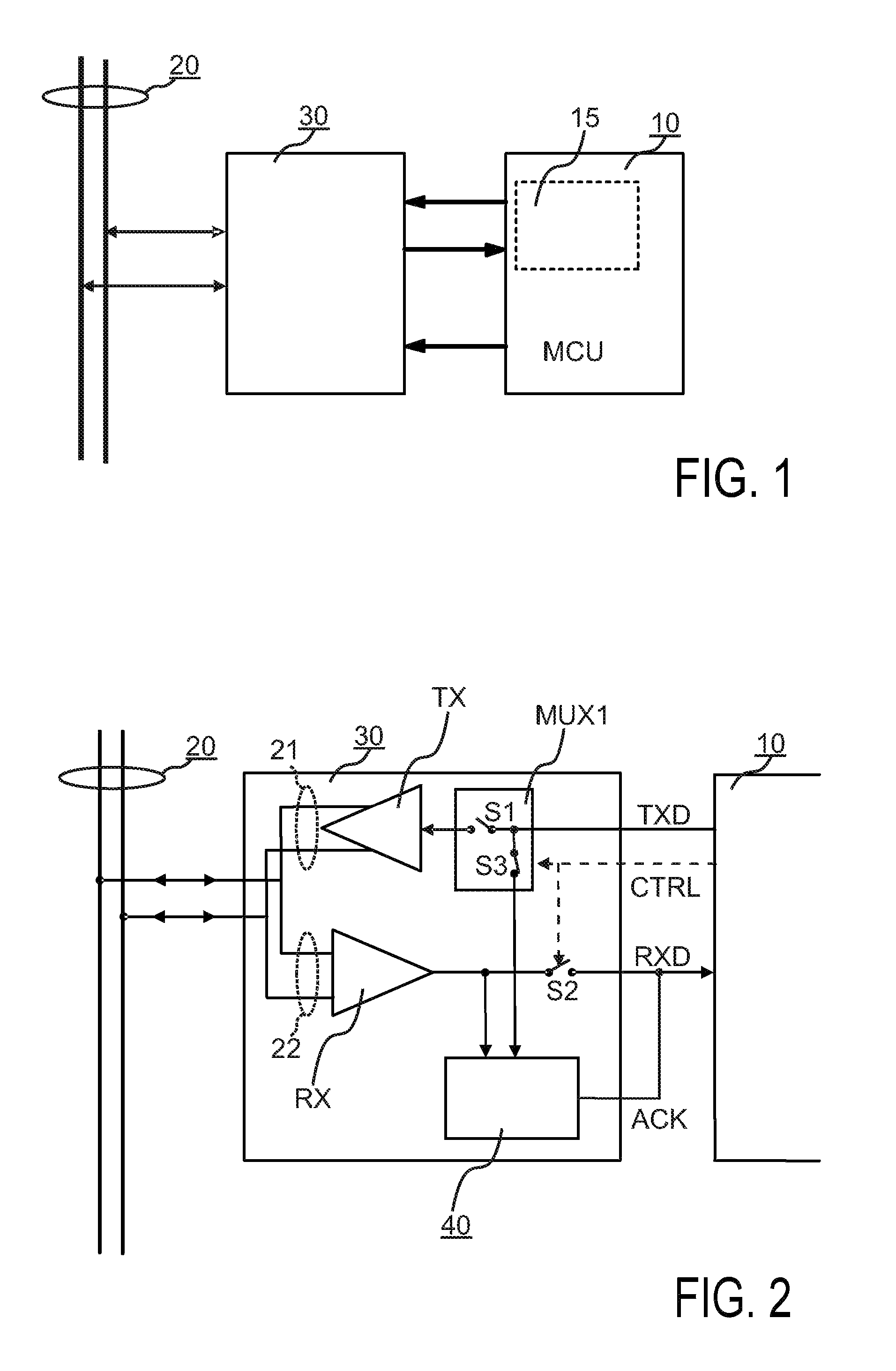
[0072]FIG. 1 shows the main application set up in which a transceiver according to the present invention may be used. In the following by way of example the improved transceiver is described with respect to a use in a controller area network (CAN); again, this invention is not limited to such a network.

[0073]Accordingly, a microcontroller unit (MCU) 10, which in general is a type of electronic control unit (ECU), which is connected via a CAN-bus 20 in order to communicate with another MCU also connected to the CAN-bus 20, for example within a automotive vehicle.

[0074]The interface between the MCUs and the CAN bus 20 is established by respective bus transceivers 30. The communication interface between the MCU 10 and the transceiver 30 is such that, in the MCU 10, an applicable configured (bus) protocol controller 15 is embedded, which handles the communication between the MCU 10 and the CAN bus 20 via the transceiver 30.

[0075]ECUs connected by the CAN-bus may typically be sensors, ac...


PUM


Abstract

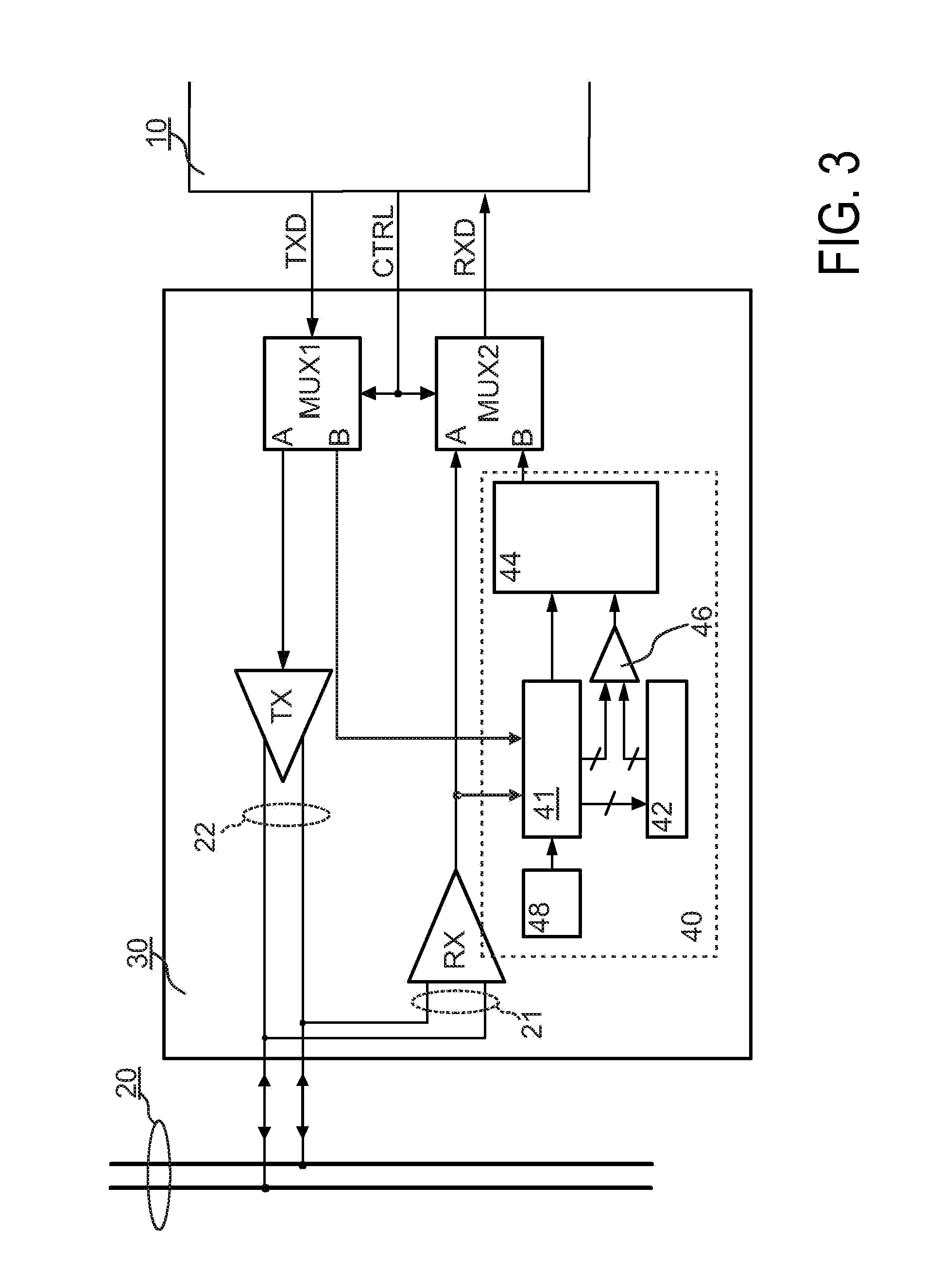
A transceiver includes a transmit pin configured to receive a signal from a microcontroller, a receive pin configured to transmit a signal to the microcontroller, at least one bus pin configured to transmit and receive signalling to or from the network, a wake-up detector, an acknowledge and / or wake-up generator, and at least one switch is operable to put the transceiver in a first mode of operation. In the first mode of operation the transmit pin is connected to the wake-up detector, and the wake-up detector is configured to activate a wake-up code in accordance with configuration information received at the transmit pin, and the receive pin is connected to an acknowledge and / or wake-up generator, which is configured to provide an acknowledge and / or wake-up signal to the receive pin based on a comparison of actual configuration information stored in the transceiver with the received configuration information from the transmit pin.

Description

FIELD OF THE INVENTION[0001]The present disclosure relates to the field of transceivers for coupling a microcontroller or a device to a network, and particularly, although not exclusively, for networks in automobiles.[0002]More particularly, the present invention relates to configuration of bus transceiversBACKGROUND OF THE INVENTION[0003]The automotive industry is actively searching for measures to reduce the CO2 emission of automotive vehicles by means of power reduction in the electronics present in such vehicles. One possible area where energy consumption could be reduced is the vehicle bus communication, in which all connected electronic control modules are kept active, just because there is bus communication. It is desired to reduce the power consumption by de-activating those control units which are not needed in certain phases of vehicle operation. This requires a new operating mode for bus transceivers, which is called “Partial Networking”.[0004]A known approach involves ex...

Claims


Application Information

Patent Timeline
Patent Type & Authority Patents(United States)
IPC IPC(8): H04B1/38
CPCY02B60/34H04L2012/40273H04L12/40039H04L12/40032H04L2012/40241H04L12/12H04L2012/40234H04L2012/40215Y02D30/50H04L12/40H04L69/32
Inventor MUTH, MATTHIAS
Owner NXP BV
Learn More