Monolithic three-dimensional semiconductor device and structure

a three-dimensional semiconductor and monolithic technology, applied in semiconductor devices, semiconductor/solid-state device details, electrical equipment, etc., can solve the problems of increasing the cost of product development, and increasing the cost of mask set costs. , to achieve the effect of reducing manufacturing costs, low flexibility, and high mask set costs

Active Publication Date: 2014-06-17
SAMSUNG ELECTRONICS CO LTD
View PDF588 Cites 58 Cited by
  • Summary
  • Abstract
  • Description
  • Claims
  • Application Information

AI Technical Summary

Benefits of technology

[0028]Embodiments of the present invention seek to provide a new method for semiconductor device fabrication that may be highly desirable for custom products. Embodiments of the current invention suggest the use of a re-programmable antifuse in conjunction with ‘Through Silicon Via’ to construct a new type of configurable logic, or as usually called, FPGA devices. Embodiments of the current invention may provide a solution to the challenge of high mask-set cost and low flexibility that exists in the current common methods of semiconductor fabrication. An additional advantage of some embodiments of the invention is that it could reduce the high cost of manufacturing the many different mask sets needed in order to provide a commercially viable logic family with a range of products each with a different set of master slices. Embodiments of the current invention may improve upon the prior art in many respects, which may include the way the semiconductor device is structured and methods related to the fabrication of semiconductor devices.
[0032]Unlike the operating transistors that are desired to operate as fast as possible, to enable fast system performance, the programming circuits could operate relatively slowly. Accordingly using a thin film transistor for the programming circuits could fit very well with the function and would reduce the needed silicon area.
[0033]The programming circuits may, therefore, be constructed with thin film transistors, which may be fabricated after the fabrication of the operating circuitry, on top of the configurable interconnection layers that incorporate and use the antifuses. An additional advantage of such embodiments of the invention is the ability to reduce cost of the high volume production. One may only need to use mask-defined links instead of the antifuses and their programming circuits. One custom via mask may be used, and this may save steps associated with the fabrication of the antifuse layers, the thin film transistors, and / or the associated connection layers of the programming circuitry.
[0050]Additionally there is a growing need to reduce the impact of inter-chip interconnects. In fact, interconnects are now dominating IC performance and power. One solution to shorten interconnect may be to use a 3D IC. Currently, the only known way for general logic 3D IC is to integrate finished device one on top of the other by utilizing Through-Silicon-Vias as now called TSVs. The problem with TSVs is that their large size, usually a few microns each, may severely limit the number of connections that can be made. Some embodiments of the current invention may provide multiple alternatives to constructing a 3D IC wherein many connections may be made less than one micron in size, thus enabling the use of 3D IC technology for most device applications.

Problems solved by technology

Semiconductor manufacturing is known to improve device density in an exponential manner over time, but such improvements come with a price.
The mask set cost required for each new process technology has also been increasing exponentially.
These changes represent an increasing challenge primarily to custom products, which tend to target smaller volume and less diverse markets therefore making the increased cost of product development very hard to accommodate.
Yet, it is always a challenge to come up with minimum set of Master Slices that will provide a good fit for the maximal number of designs because it is quite costly if a dedicated mask set is required for each product.
The difficulty to provide variable-sized array structure devices is due to the need of providing I / O cells and associated pads to connect the device to the package.
This method places a severe limitation on the I / O cell to use the same type of transistors as used for the logic and; hence, would not allow the use of higher operating voltages for the I / O.
These circuits are complex and require a far larger silicon area than conventional I / Os.
This implies that even the use of the borderless logic array of the prior art will still require multiple expensive mask sets.
However, unlike vias that are made with the same metal that is used for the interconnection, these antifuses generally use amorphous silicon and some additional interface layers.
In fact, it seems that no one is advancing Antifuse FPGA devices anymore.
One of the severe disadvantages of antifuse technology has been their lack of re-programmability.
Another disadvantage has been the special silicon manufacturing process required for the antifuse technology which results in extra development costs and the associated time lag with respect to baseline IC technology scaling.
The general disadvantage of common FPGA technologies is their relatively poor use of silicon area.
Integrating top layer transistors above an insulation layer is not common in an IC because the quality and density of prior art top layer transistors are inferior to those formed in the base (or substrate) layer.
The problem with TSVs is that they are relatively large (a few microns each in area) and therefore may lead to highly limited vertical connectivity.
In particular, yield and reliability of extremely complex three dimensional systems will have to be addressed, particularly given the yield and reliability difficulties encountered in building complex Application Specific Integrated Circuits (ASIC) of recent deep submicron process generations.
The problem with TSVs is that their large size, usually a few microns each, may severely limit the number of connections that can be made.

Method used


Image

  • Monolithic three-dimensional semiconductor device and structure
  • Monolithic three-dimensional semiconductor device and structure
  • Monolithic three-dimensional semiconductor device and structure

Examples


Embodiment Construction

[0236]Embodiments of the present invention are now described with reference to the drawing figures. Persons of ordinary skill in the art will appreciate that the description and figures illustrate rather than limit the invention and that in general the figures are not drawn to scale for clarity of presentation. Such skilled persons will also realize that many more embodiments are possible by applying the inventive principles contained herein and that such embodiments fall within the scope of the invention which is not to be limited except by the appended claims.

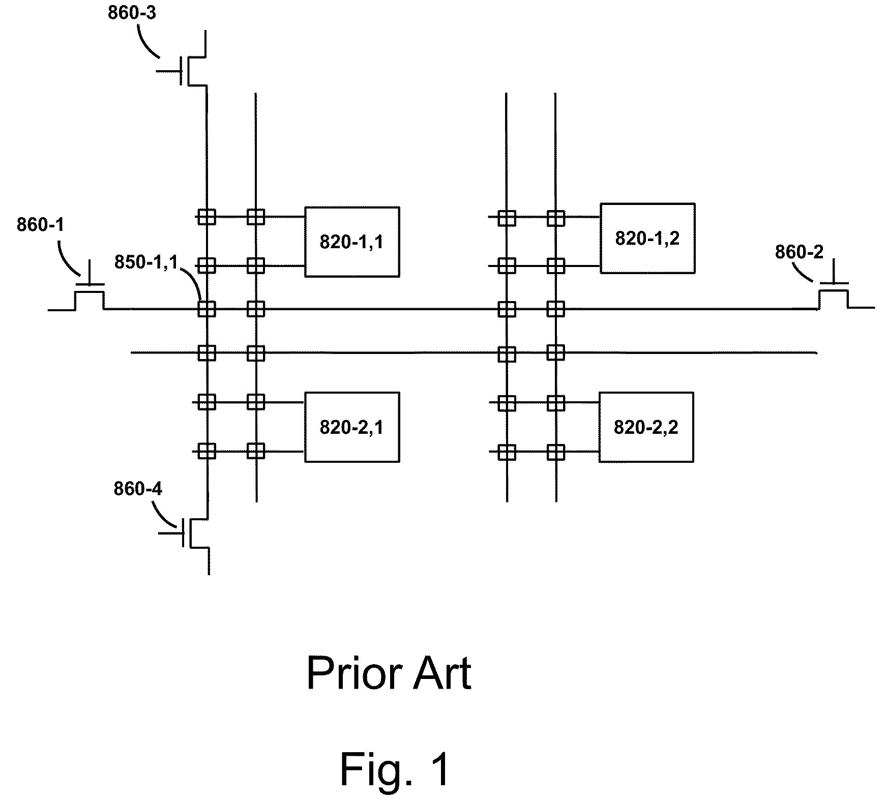
[0237]FIG. 1 illustrates a circuit diagram illustration of a prior art, where, for example, 860-1 to 860-4 are the programming transistors to program antifuse 850-1,1.

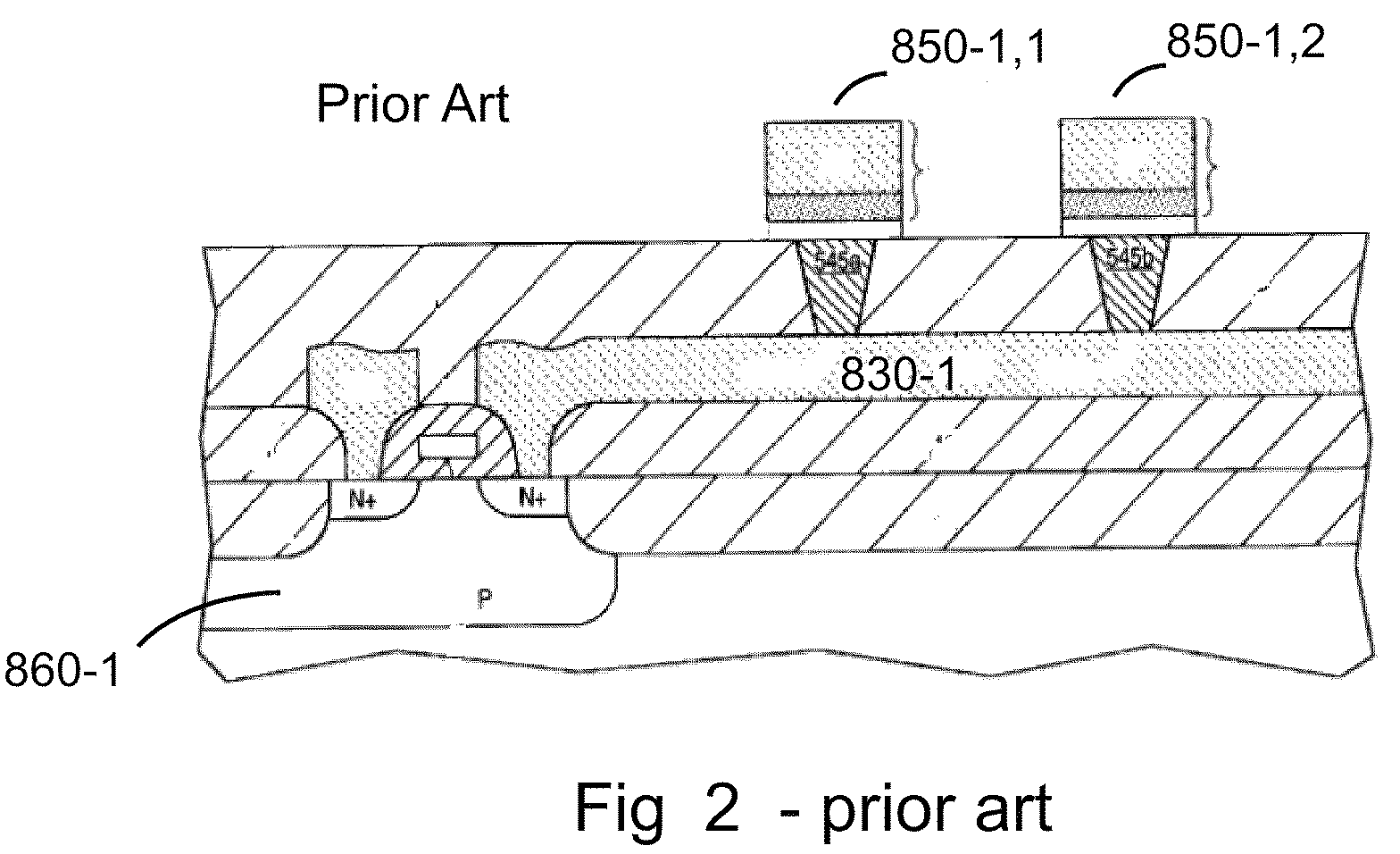
[0238]FIG. 2 is a cross-section illustration of a portion of a prior art represented by the circuit diagram of FIG. 1 showing the programming transistor 860-1 built as part of the silicon substrate.

[0239]FIG. 3A is a drawing illustration of a programmable interc...


PUM


Abstract

A semiconductor device includes a first mono-crystallized layer including first transistors, and a first metal layer forming at least a portion of connections between the first transistors; and a second layer including second transistors, the second transistors including mono-crystalline material, the second layer overlying the first metal layer, wherein the first metal layer includes aluminum or copper, and wherein the second layer is less than one micron in thickness and includes logic cells.

Description

CROSS-REFERENCE OF RELATED APPLICATION[0001]This application claims priority of co-pending U.S. patent application Ser. Nos. 12 / 423,214, 12 / 577,532, 12 / 706,520, 12 / 792,673, 12 / 847,911, 12 / 859,665, and 12 / 900,379 the contents of which are incorporated by reference.BACKGROUND OF THE INVENTION[0002]1. Field of the Invention[0003]The present invention relates to the general field of Integrated Circuit (IC) devices and fabrication methods, and more particularly to multilayer or Three Dimensional Integrated Circuit (3D IC) devices and fabrication methods.[0004]2. Discussion of Background Art[0005]Semiconductor manufacturing is known to improve device density in an exponential manner over time, but such improvements come with a price. The mask set cost required for each new process technology has also been increasing exponentially. While 20 years ago a mask set cost less than $20,000, it is now quite common to be charged more than $1M for today's state of the art device mask set.[0006]Thes...

Claims


Application Information

Patent Timeline
Patent Type & Authority Patents(United States)
IPC IPC(8): H01L27/118H01L23/544H01L27/11H01L27/12H01L27/02H01L27/112H01L21/84H01L27/06H01L27/105H01L23/48H01L21/822H01L29/78H01L29/40H01L27/115H01L29/66H01L21/762H01L27/108
CPCH01L27/11551H01L23/481H01L27/1108H01L2224/48227H01L2924/15311H01L27/10894H01L27/10897H01L27/11578H01L2224/48091H01L27/10879H01L21/76254H01L29/78H01L2224/73204H01L27/105H01L2924/3025H01L23/544H01L27/0688H01L27/112H01L2924/13091H01L2224/16145H01L2924/01322H01L2924/10253H01L2224/32225H01L2223/54426H01L2224/73265H01L27/11521H01L27/11807H01L27/11H01L2924/3011H01L27/10876H01L2224/16225H01L27/1203H01L2224/45124H01L27/0207H01L29/66795H01L2224/32145H01L27/11898H01L21/84H01L21/8221H01L2924/00011H01L2924/12032H01L2924/1301H01L2924/1305H01L2924/13062H01L2924/181H01L2224/73253H10B12/056H10B12/50H10B12/053H10B12/09H10B10/125H10B10/00H10B20/00H10B41/30H10B41/20H10B43/20H01L2924/00H01L2924/00014H01L2224/80001H01L2924/00012
Inventor OR-BACH, ZVICRONQUIST, BRIANBEINGLASS, ISRAELDE JONG, JAN LODEWIJKSEKAR, DEEPAK C.
Owner SAMSUNG ELECTRONICS CO LTD
Why Eureka
Try Eureka