
Charging member, process cartridge and electrophotographic apparatus

a technology of electrophotography apparatus and charging member, which is applied in the direction of electrographic process, instruments, corona discharge, etc., can solve the problems of charging member wear and difficulty in some cases in keeping empty space, and achieve the effect of improving wear resistan

Active Publication Date: 2014-06-17
CANON KK
View PDF22 Cites 14 Cited by
  • Summary
  • Abstract
  • Description
  • Claims
  • Application Information

AI Technical Summary

Benefits of technology

The present invention is about improving the performance of charging members in electrophotographic apparatuses. The invention provides a charging member with a surface layer that is resistant to wear and has elasticity to create a stable nip between it and the photosensitive member. This results in high-quality electrophotographic images over a long period of time. The technical effects of this invention include reducing wear and tear on the charging member and photosensitive member, and ensuring consistent and uniform charging.

Problems solved by technology

H08-179591 can keep the photosensitive member and the charging member from wearing because the both are not in contact with each other, but has been found to have difficulty in some cases in keeping the empty space.
The method according to Japanese Patent Application Laid-open No. 2004-020844 has been found to have difficulty in some cases in making the charging member always wear and charging the photosensitive member constantly and uniformly.

Method used

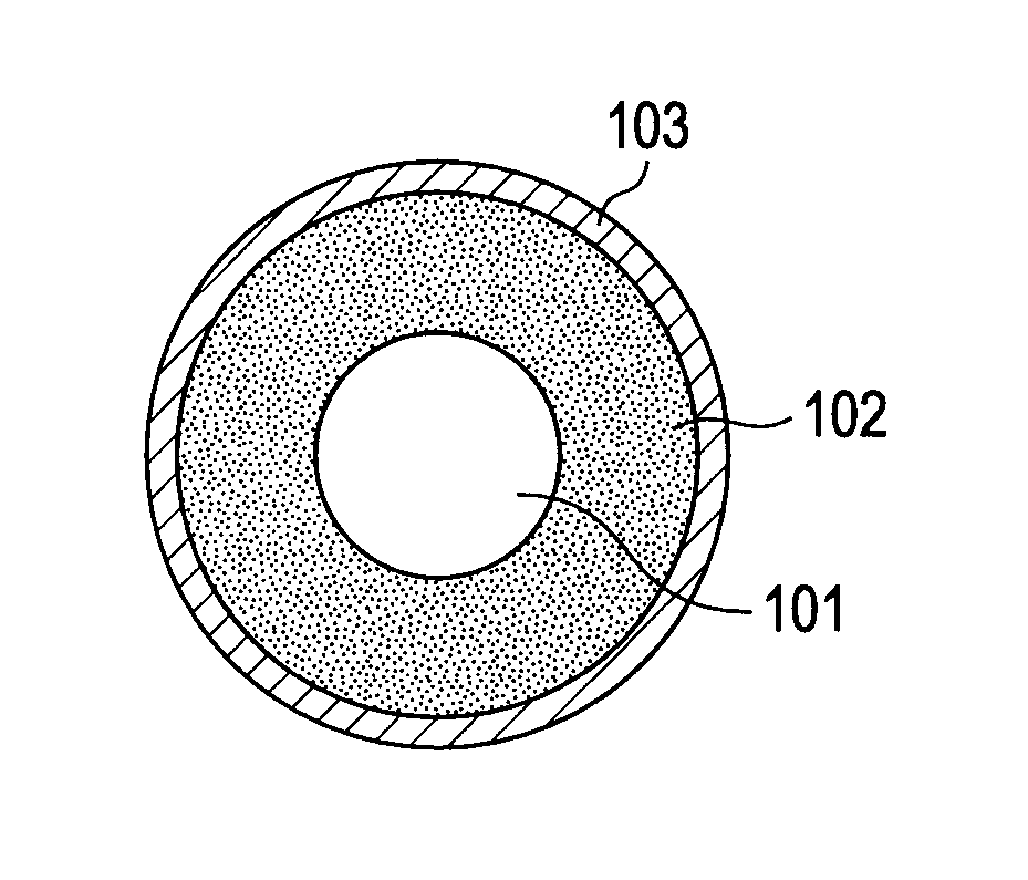
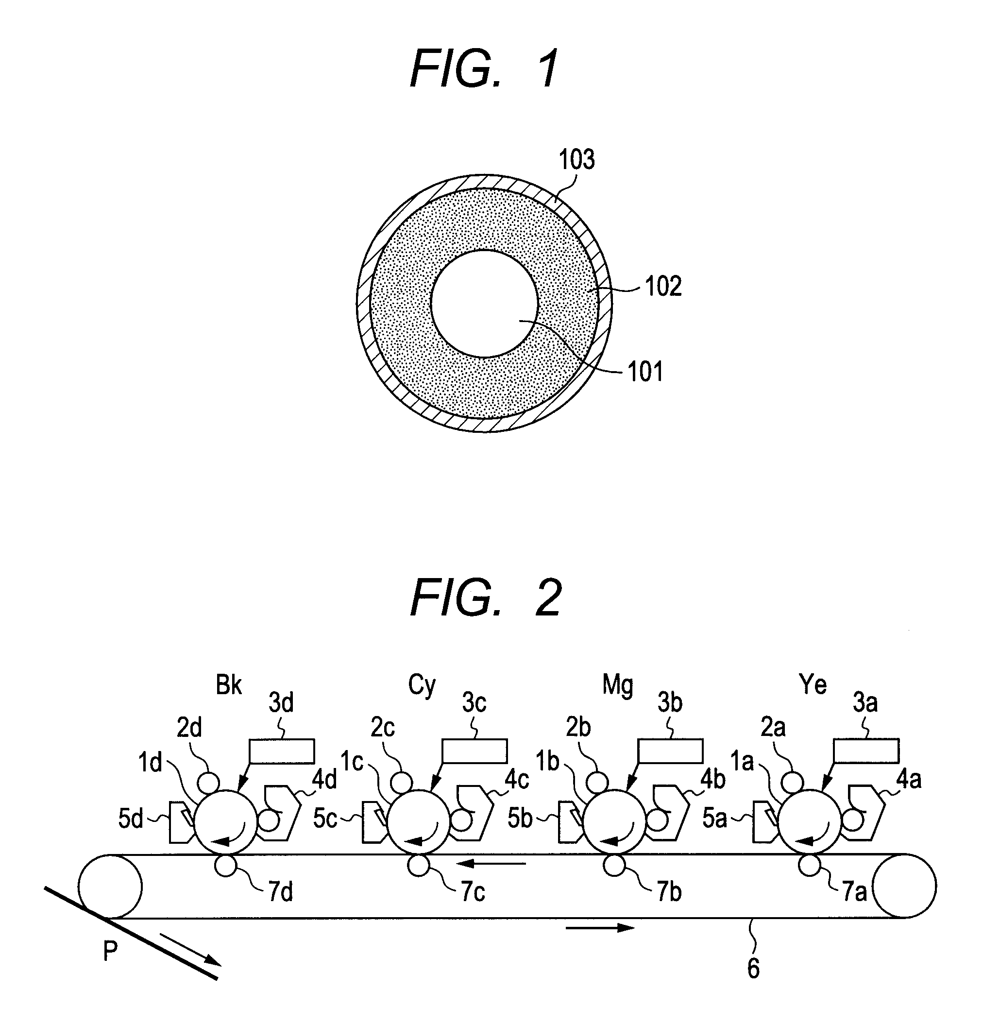

Image

  • Charging member, process cartridge and electrophotographic apparatus
  • Charging member, process cartridge and electrophotographic apparatus
  • Charging member, process cartridge and electrophotographic apparatus

Examples


example 1

Formation of Elastic Layer

[0116]Components shown in Table 1 below were mixed by means of a 6-liter pressure kneader (TD6-15MDX; manufactured by Toshin Co., Ltd.) for 24 minutes in a packing of 70 vol. % and at a number of blade revolutions of 30 rpm to obtain an unvulcanized rubber composition.

[0117]

TABLE 1Medium / high-nitrile NBR100 parts(trade name: NIPOL DN219; boundacrylonitrile content center value: 33.5%;Mooney viscosity center value: 27;available from Nippon Zeon Co., Ltd.)Carbon black for color (filler)48 parts(trade name: TOKA BLACK #7360SB;particle diameter: 28 nm; nitrogenadsorption specific surface area: 77 m2 / g;DBP oil absorption: 87 cm3 / 100 g;available from Tokai Carbon Co., Ltd.)Calcium carbonate (filler)20 parts(trade name: NANOX #30; availablefrom Maruo Calcium Co., Ltd.)Zinc oxide5 partsStearic acid1 part

[0118]To 174 parts by mass of this unvulcanized rubber composition, 4.5 parts of tetrabenzylthiuram disulfide (trade name: SANCELER TBzTD; available from Sanshin Ch...

examples 2 to 32

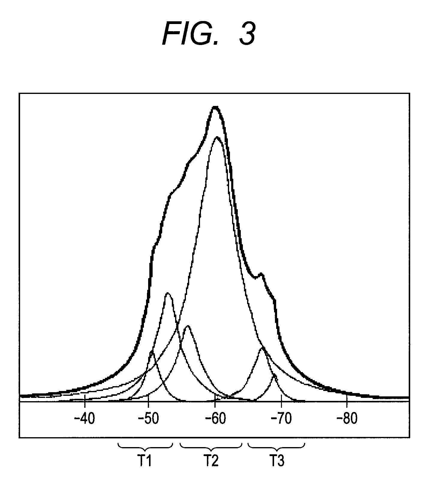
[0172]Condensates were prepared in the same way as Example 1 except that the raw materials to be used were changed for those shown in Table 3. The products were evaluated in the same way. Charging rollers were also produced in the same way as Example 1 except that the respective condensation products were used. The rollers were evaluated in the same way. The ROR and the value of Hf / Si are shown in Table 3, and the results of evaluation in Table 5. About hydrolyzable silane compounds and hydrolyzable hafnium compounds for which the symbols represent in Table 3, their specific structures and manufacturers are shown in Table 4.


PUM

PropertyMeasurementUnit
electrical resistanceaaaaaaaaaa
DC voltageaaaaaaaaaa

Abstract

A charging member is provided with a surface layer that can not easily wear even due to its contact with a photosensitive member and also has an appropriate elasticity contributing to the formation of an appropriate nip between it and the photosensitive member. The charging member has a substrate, an elastic layer and a surface layer; the surface layer containing a high-molecular compound having an Si—O—Hf linkage and having a constitutional unit represented by the formula (1) and a constitutional unit represented by the formula (2):

Description

CROSS-REFERENCE TO RELATED APPLICATIONS[0001]This application is a continuation of International Application No. PCT / JP2011 / 005143, filed Sep. 13, 2011, which claims the benefit of Japanese Patent Application No. 2010-215808, filed Sep. 27, 2010.BACKGROUND OF THE INVENTION[0002]1. Field of the Invention[0003]This invention relates to a charging member and a process cartridge making use of the same.[0004]2. Description of the Related Art[0005]As a charging member used for contact charging of an electrophotographic photosensitive member, a charging member having a support, a conductive elastic layer provided on the support and an insulative surface layer provided on the conductive elastic layer is in wide use.[0006]Now, the charging member used in such a contact charging system is kept in contact with the photosensitive member, and hence the former's surface may be scraped by any toners, external additives and so forth which remain on the surface of the photosensitive member, so that ...

Claims


Application Information

Patent Timeline
Patent Type & Authority Patents(United States)
IPC IPC(8): G03G15/02
CPCC08L85/00G03G15/0233Y10T428/31667Y10T428/31663C08G65/337G03G15/02
Inventor NAGAMINE, NORIKOKURODA, NORIAKITOMOMIZU, YUYA
Owner CANON KK
Learn More