Flow measuring device

a technology of flow measurement and measuring device, which is applied in the direction of measurement device, volume/mass flow measurement, instruments, etc., can solve the problems of reducing the accuracy of air flow measurement, measuring errors in air flow measurement values, and deviations in output signals, so as to reduce the width of the passage and reduce the cross-sectional area of the passage.

Active Publication Date: 2014-06-24
DENSO CORP
View PDF11 Cites 10 Cited by
  • Summary
  • Abstract
  • Description
  • Claims
  • Application Information

AI Technical Summary

Benefits of technology

[0013]According to the present invention, there is provided a flow measuring device including a housing, a support, and a flow measurement element. The housing defines a passage therein and includes a passage narrowing part, which reduces a cross-sectional area of the passage, in a predetermined part of the passage. The support has a platy shape and is disposed along a flow direction of fluid flowing in the passage. The flow measurement element is located inside the passage narrowing part and is disposed on a surface of the support. The flow measurement element is configured to detect a flow rate of fluid flowing in the passage. The passage narrowing part has an inner wall surface that gradually reduces a width of the passage from a center side to both end sides of the passage in a height direction of the passage, which is perpendicular to a direction of the width of the passage.

Problems solved by technology

In this case, the sensor output signal fluctuates and a measuring error is observed in an air flow measurement value.
For this reason, a defect of reduction in air flow measurement accuracy occurs.
In this case, a wide flow-rate measuring range from a high flow rate to an extremely low flow rate is necessary, but in the air flow measuring device described in Patent Documents 1 and 2, the expansion of the air flow measuring range to the low air flow rate region is limited.
In the air flow measuring device disclosed in Patent Document 3 (JP2005-128038A), because the outer circumferential wall surface of the entire bypass passage has the above-described shape, limitation of output fluctuation of a sensing element is possible, but the limitation of the output fluctuation of the sensing element and expansion of a flow-rate measuring range are incompatible.

Method used


Image

  • Flow measuring device
  • Flow measuring device
  • Flow measuring device

Examples


first embodiment

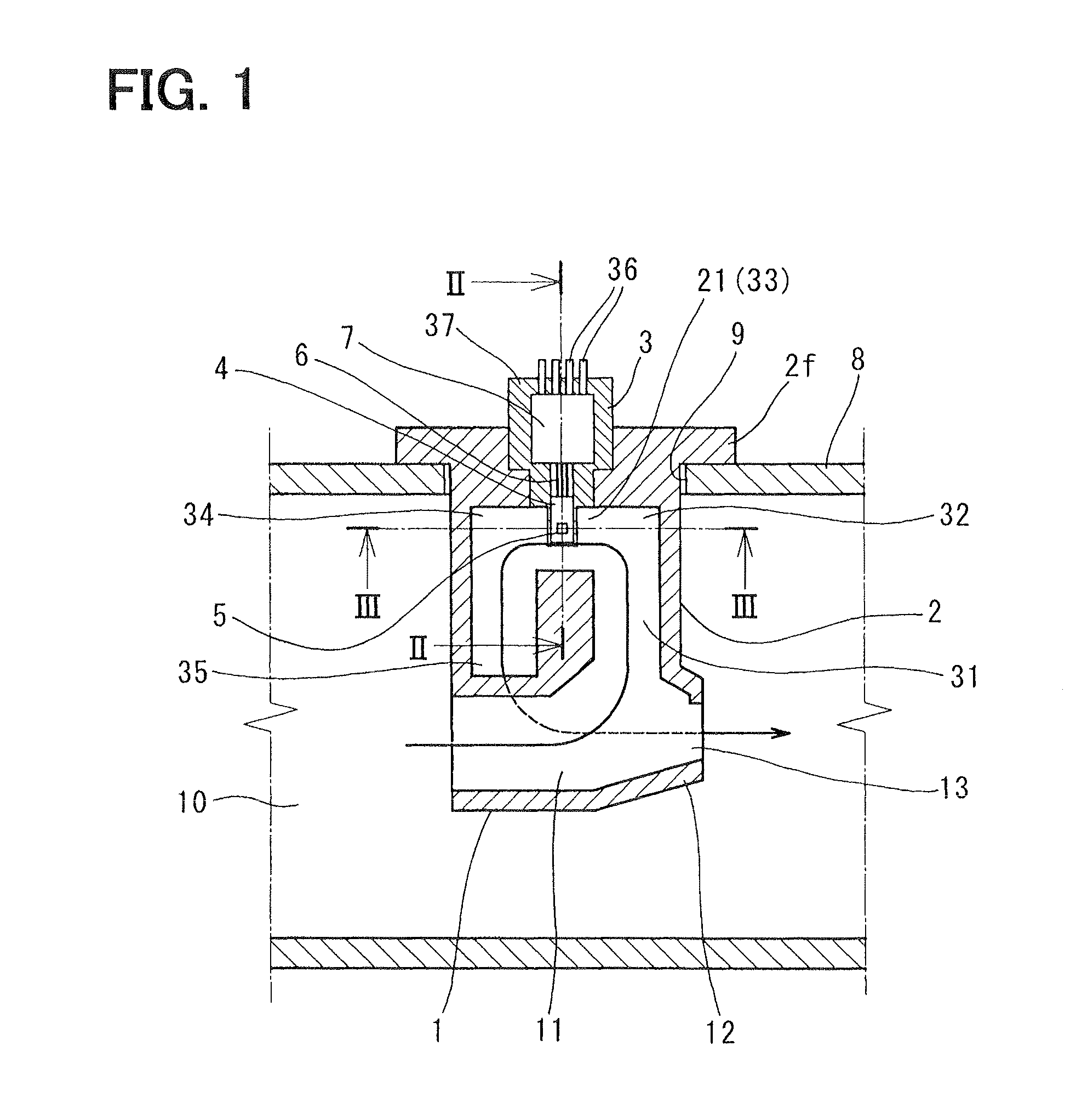
[0039]A configuration of a first embodiment will be described below. FIGS. 1 to 4B show the first embodiment.

[0040]A controlling device (engine controlling system) of an internal combustion according to the first embodiment includes an air flow measuring device which measures (calculates) a flow rate (air flow rate) of intake air supplied to a combustion chamber of the internal combustion (engine) having cylinders. The air flow measuring device includes a heat generating resistance type air flow meter (a flow rate sensor module or a thermal type air flow meter: hereinafter referred to as an air flow meter or an AFM) and an engine controlling unit (an engine controlling device: hereinafter referred to as an ECU). The AFM outputs an electrical signal in accordance with the flow rate of the intake air flowing in the intake pipe of the engine. The ECU measures (calculates) a flow rate or a flow velocity of air suctioned into the combustion chamber of each cylinder of the engine based on...

second embodiment

[0068]In the second embodiment, as illustrated in FIGS. 5A to 6B, the air flow measuring device in which the sensing element 5 is directly mounted on the surface of the sensor support 3 is drawn. But the air flow measuring device, in which the sensor chip 4 is mounted on the sensor chip mounting area of the sensor support 3 and then the sensing element 5 is disposed on the surface of the sensor chip 4, will be described as the second embodiment.

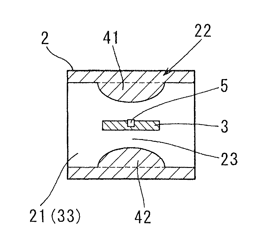
[0069]In a block 2 of a sensor body of the present embodiment, as illustrated in FIGS. 5A to 6B, the passage narrowing part 22, in which an air flow sensor is contained, is provided. Along a bypass passage 21, a narrowing passage 23 surrounded by the passage narrowing part 22 is defined. As shown in FIG. 5A, the passage narrowing part 22 includes three projecting walls 41 to 43 projecting from an inner wall surface of the block 2 to a center of the narrowing passage 23, and the narrowing passage 23 is defined between inner wall surfaces of th...

third embodiment

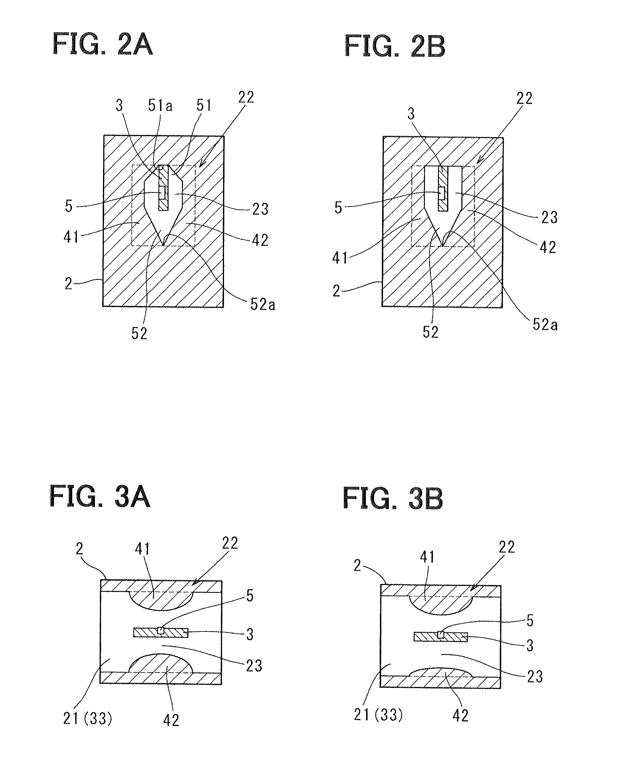
[0075]FIGS. 7A to 8B show a third embodiment of the invention. In the third embodiment, as illustrated in FIGS. 7A to 8B, an air flow measuring device in which a sensing element 5 is directly mounted on a surface of a sensor support 3 is drawn. But the air flow measuring device, in which a sensor chip 4 is mounted on a sensor chip mounting area of the sensor support 3 and then the sensing element 5 is disposed on the surface of the sensor chip 4, will be described as the third embodiment.

[0076]In a block 2 of a sensor body of the present embodiment, as illustrated in FIGS. 7A to 8B, the passage narrowing part 22, in which an air flow sensor is contained, is provided. Along a bypass passage 21, a narrowing passage 23 surrounded by the passage narrowing part 22 is defined. As shown in FIGS. 7A to 8B, the passage narrowing part 22 includes at least two projecting walls 41 and 42 projecting from an inner wall surface of the block 2 to a center of the narrowing passage 23, and the narrow...


PUM


Abstract

A flow measuring device includes a housing, a support, and a flow measurement element. The housing defines a passage therein and includes a passage narrowing part, which reduces a cross-sectional area of the passage, in a predetermined part of the passage. The support has a platy shape and is disposed along a flow direction of fluid flowing in the passage. The flow measurement element is located inside the passage narrowing part and is disposed on a surface of the support. The flow measurement element detects a flow rate of fluid flowing in the passage. The passage narrowing part has an inner wall surface that gradually reduces a width of the passage from a center side to both end sides of the passage in a height direction of the passage, which is perpendicular to a direction of the width of the passage.

Description

CROSS REFERENCE TO RELATED APPLICATION[0001]This application is based on and incorporates herein by reference Japanese Patent Application No. 2010-241692 filed on Oct. 28, 2010.BACKGROUND OF THE INVENTION[0002]1. Field of the Invention[0003]The present invention relates to a flow measuring device that includes a flow measuring element, such as a heater resistive element or a sensing resistive element, disposed on a surface of its support attached to a housing.[0004]2. Description of Related Art[0005]A conventional technology will be described below. Conventionally, an air flow measuring device including an air flow meter detachably attached to an attaching hole of an intake pipe is public knowledge. The intake pipe defines an intake air passage of an internal combustion (engine). The air flow meter includes, as illustrated in FIG. 10, a sensor body 101, a sensor support 102, and an air flow sensor. The sensor body 101 is attached such that the sensor body 101 projects into the intak...

Claims


Application Information

Patent Timeline
Patent Type & Authority Patents(United States)
IPC IPC(8): G01F1/68
CPCG01F1/6842G01F15/14
Inventor GOKA, YASUSHIENOMOTO, TAKASHIKITAHARA, NOBORU
Owner DENSO CORP
Why Eureka
Try Eureka