

Air pressure information display system of vehicle tire
- Summary
- Abstract
- Description
- Claims
- Application Information
AI Technical Summary
Benefits of technology
Problems solved by technology
Method used
Image

Examples
first embodiment
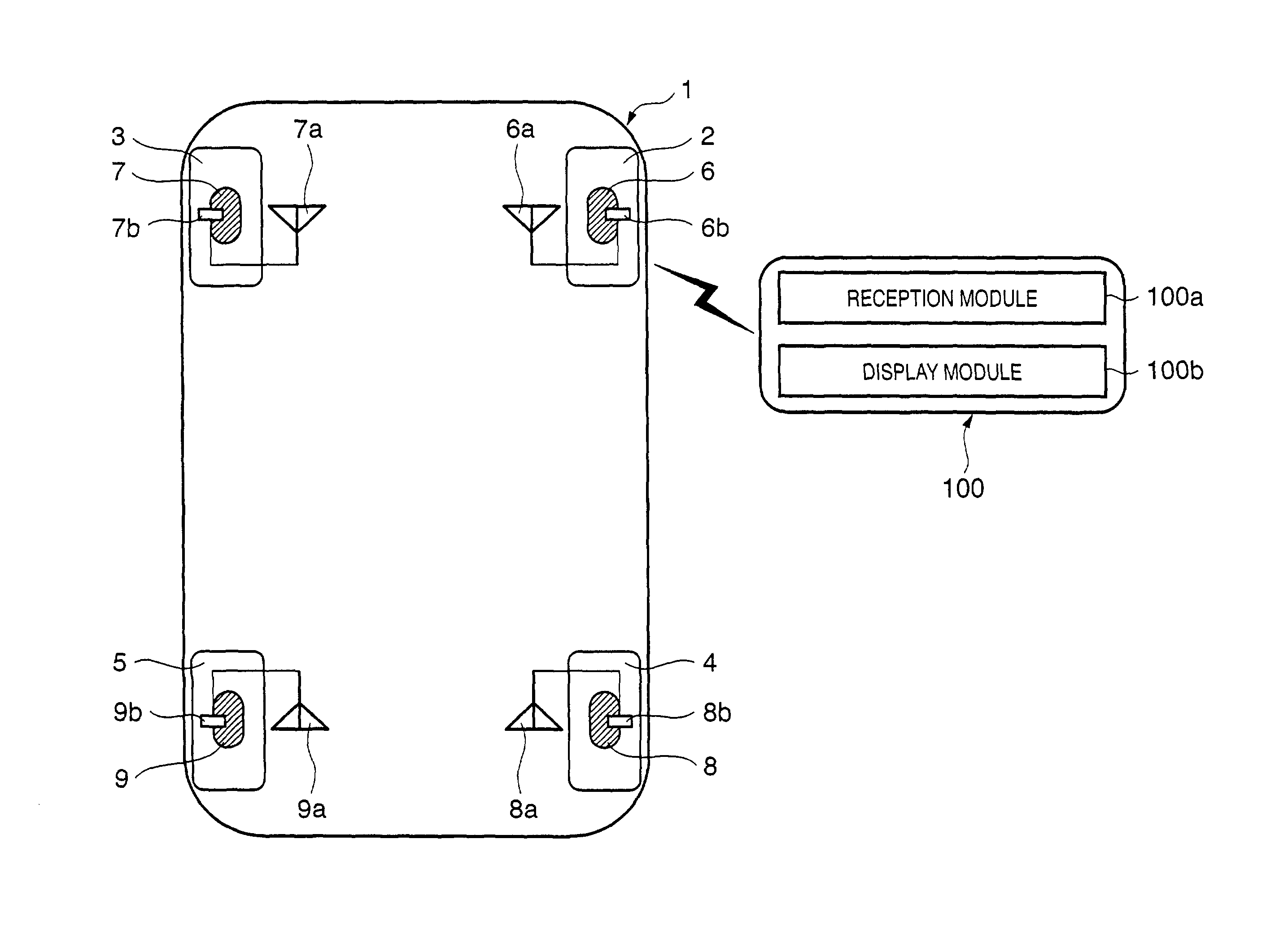
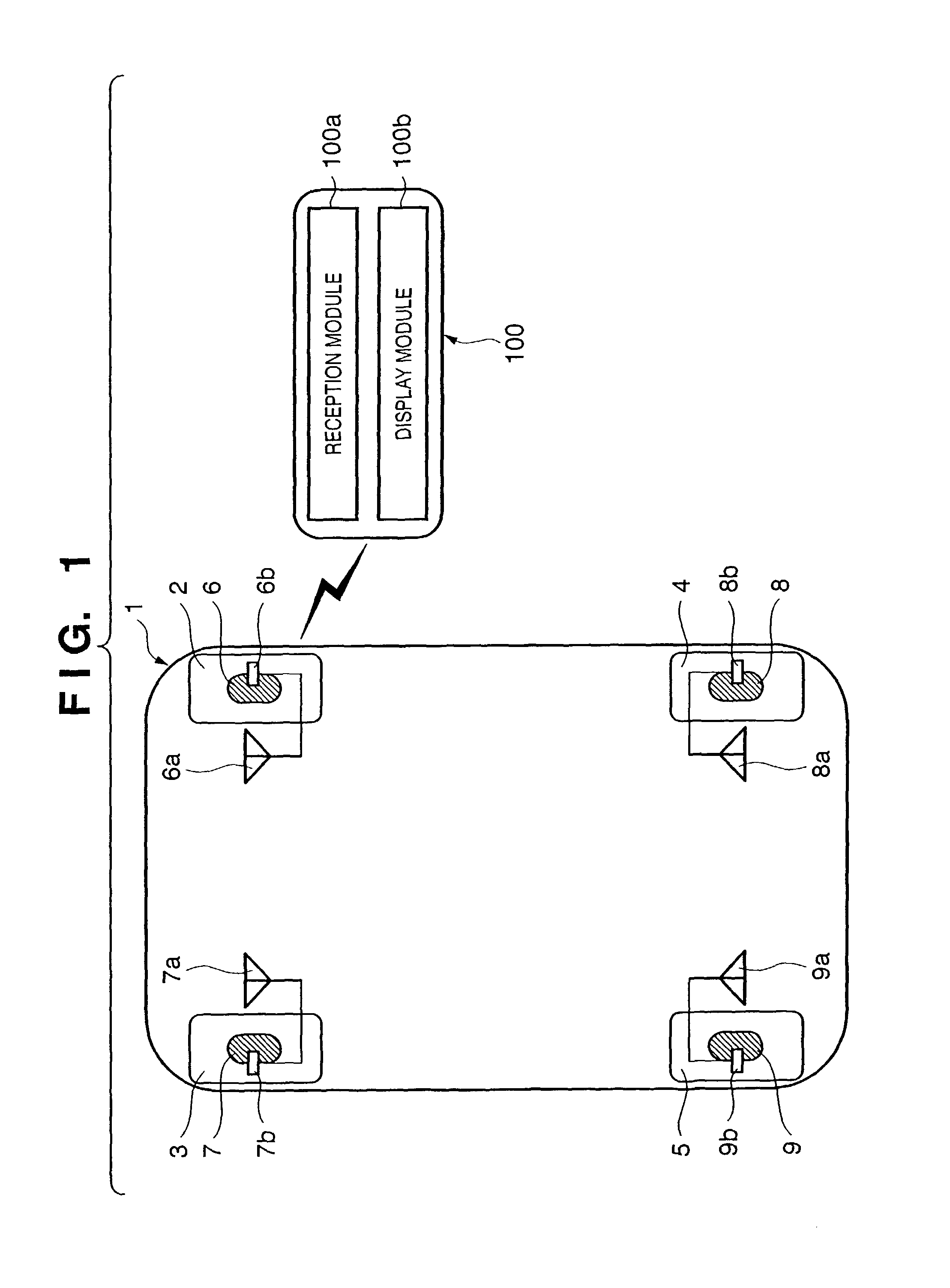
[0082]FIG. 1 shows the overall arrangement of an air pressure display system of a vehicle tire according to the first embodiment. Referring to FIG. 1, a vehicle 1 has tires 2 to 5, which respectively comprise air pressure sensors 6 to 9. The air pressure sensors 6 to 9 can detect not only an air pressure but also a tire temperature.
[0083]The air pressure sensors 6 to 9 respectively form sensor units which comprise transmitters 6b to 9b and antennas 6a to 9a, and the air pressure (measured air pressure) and tire temperature detected by the air pressure sensors are transmitted to an informing unit installed in a specific facility (e.g., gas station) 100 via a wireless communication.
[0084]In this embodiment, the antenna is equipped in correspondence with each air pressure sensor, but data of the respective air pressure sensors may be sent using only one antenna.
[0085]An informing unit 100 installed in the specific facility such as a gas station or the like comprises a reception module ...
second embodiment
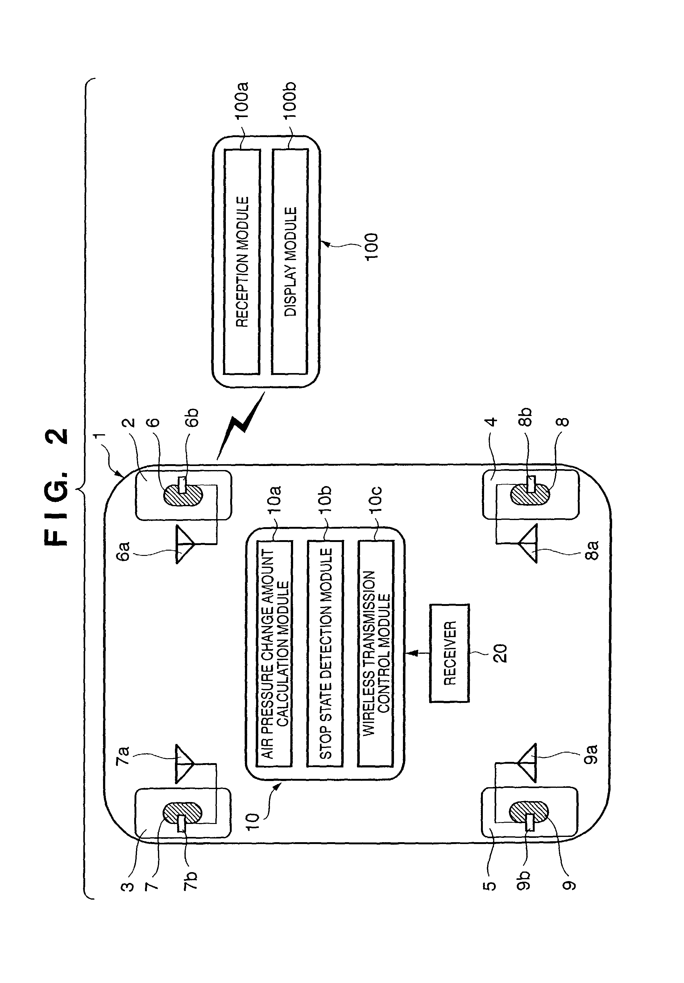
[0087]FIG. 2 shows the overall arrangement of an air pressure display system of a vehicle tire according to the second embodiment. Referring to FIG. 2, a vehicle 1 has tires 2 to 5, which respectively comprise air pressure sensors 6 to 9.
[0088]The air pressure sensors 6 to 9 respectively form sensor units which comprise transmitters 6b to 9b and antennas 6a to 9a, and the air pressure (measured air pressure) and tire temperature detected by the air pressure sensors are transmitted to a control unit 10 mounted on the vehicle 1 or an informing unit 100 installed in a specific facility (e.g., gas station) via wireless communications.
[0089]In the following description, the informing unit 100 installed in the specific facility such as a gas station or the like will also be referred to as “gas station 100” for the sake of convenience.
[0090]The control unit 10 implements functions of respective modules to be described below by executing operation instructions of a software program, which i...
third embodiment
[0110]FIG. 5 shows the overall arrangement of an air pressure display system of a vehicle tire according to the third embodiment. Referring to FIG. 5, a vehicle 1 has tires 2 to 5, which respectively comprise air pressure sensor units 61, 71, 81, and 91.
[0111]The air pressure sensor units 61, 71, 81, and 91 respectively comprise air pressure sensors 6 to 9, antennas 6a to 9a, transmission modules 6b to 9b (corresponding to the transmitters 6b to 9b in the first and second embodiments) for transmitting the air pressure and tire temperature detected by the air pressure sensors to a gas station 100 as a specific facility (to be described later), and reception modules 6c to 9c for receiving an air pressure information transmission request signal from the gas station 100.
[0112]In this embodiment as well, the air pressure sensors 6 to 9 can detect not only the air pressure but also the tire temperature.
[0113]The gas station (i.e., an informing unit installed in the specific facility) 100 ...
PUM
 Abstract
Description
Claims
Application Information