Computer system and storage migration method utilizing acquired apparatus specific information as virtualization information
a computer system and storage technology, applied in computing, input/output to record carriers, instruments, etc., can solve problems such as business operations that must be stopped, and achieve the effect of simplifying the migration process of storage apparatuses and avoiding the performance degradation of the overall system
- Summary
- Abstract
- Description
- Claims
- Application Information
AI Technical Summary
Benefits of technology
Problems solved by technology
Method used
Image
Examples
first embodiment
(1) First Embodiment
(1-1) Configuration of Computer System in Present Embodiment
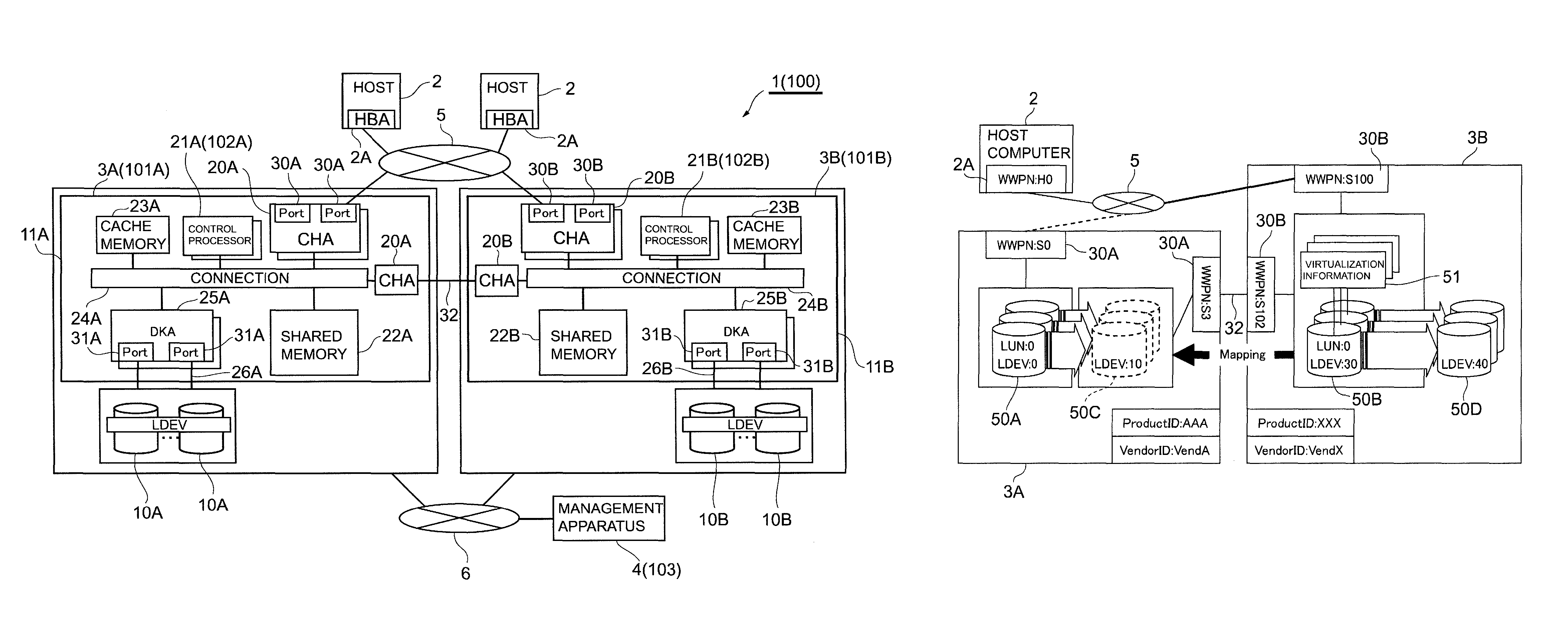
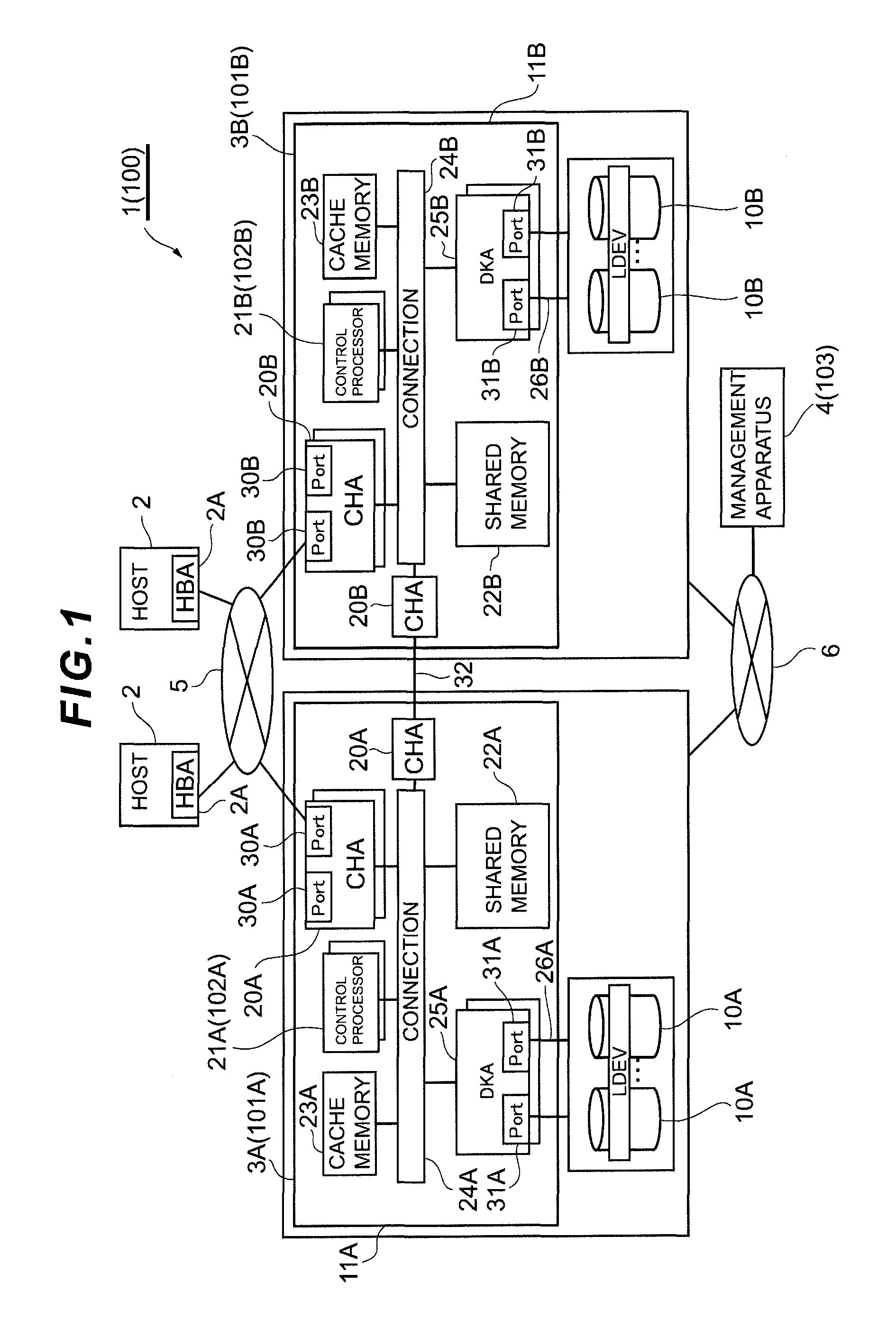
[0052]FIG. 1 shows the overall computer system 1 according to this embodiment. The computer system 1 comprises a plurality of host computers 2, two storage apparatuses 3A, 3B, and a management apparatus 4. The respective host computers 2 are each connected to the storage apparatuses 3A, 3B via a SAN (Storage Area Network) 5, and the two storage apparatuses 3A, 3B are connected to the management apparatus 4 via a LAN (Local Area Network) 6.
[0053]The host computer 2 is a computer device comprising information processing resources such as a processor and a memory and is configured, for example, from a personal computer, a workstation, a mainframe or the like. The host computer 2 comprises an input device such as a keyboard, a switch, a pointing device and / or a microphone, and an output device such as a monitor display and / or a speaker, and is connected to the SAN 5 via an HBA (Host Bus Adapter) 2A.
[0054]The...
second embodiment
(2) Second Embodiment
[0171]FIG. 21 with the same reference numerals for the portions corresponding to those in FIG. 1 shows the computer system 90 according to the second embodiment. The computer system 90 is configured the same as the computer system 1 according to the first embodiment excluding the point that a storage apparatus (this is hereinafter referred to as the “external storage apparatus”) 92 is externally connected to the migration source storage apparatus 91A.
[0172]FIG. 22 shows the outline off the storage migration method according to the second embodiment (this is hereinafter referred to as the “second storage migration method”). In FIG. 22, the same reference numerals are given to the portions corresponding to those of FIG. 5. If the external storage apparatus 92 is externally connected to the migration source storage apparatus 91A, as described above with reference to FIG. 4, a virtual device 50F mapped with the logical device (this is hereinafter referred to as the ...
third embodiment
(3) Third Embodiment
[0196]In FIG. 1, reference numeral 100 shows the computer system according to the third embodiment. The computer system 100 is configured the same as the computer system 1 according to the first embodiment excluding the point that the migration source storage apparatus 101A is not equipped with the external connection function and, consequently, the processing contents of the storage migration method of migrating a storage apparatus from the migration source storage apparatus 101A to the migration destination storage apparatus 101B are different.
[0197]FIG. 26 with the same reference numerals for the portions corresponding to those in FIG. 5 shows the outline off the storage migration method according to the third embodiment (this is hereinafter referred to as the “third storage migration method”). If the migration source storage apparatus 101A is not equipped with the external connection function, the migration destination logical device 50B cannot be mapped as a...
PUM
 Abstract
Description
Claims
Application Information
 - R&D
- Intellectual Property
- Life Sciences
- Materials
- Tech Scout
- Unparalleled Data Quality
- Higher Quality Content
- 60% Fewer Hallucinations
Browse by: Latest US Patents, China's latest patents, Technical Efficacy Thesaurus, Application Domain, Technology Topic, Popular Technical Reports.
© 2025 PatSnap. All rights reserved.Legal|Privacy policy|Modern Slavery Act Transparency Statement|Sitemap|About US| Contact US: help@patsnap.com


