Eureka AIR delivers breakthrough ideas for toughest innovation challenges, trusted by R&D personnel around the world.

Exhaust gas treatment device for diesel engine

a technology for exhaust gas treatment and diesel engines, which is applied in the direction of exhaust treatment electric control, combustion types, separation processes, etc., can solve the problems of difficult heat transfer of the heater, the generation of combustible gas may not be smoothly started, and the difficulty in starting the heat of the heater, so as to reduce the size of the combustible gas generator and the effect of smooth starting

Active Publication Date: 2014-07-01
KUBOTA CORP
View PDF10 Cites 1 Cited by
  • Summary
  • Abstract
  • Description
  • Claims
  • Application Information

AI Technical Summary

Benefits of technology

[0020]The Invention According to Claim 1 exhibits the following effects.
[0021]Effect The generation of a combustible gas can be smoothly started.
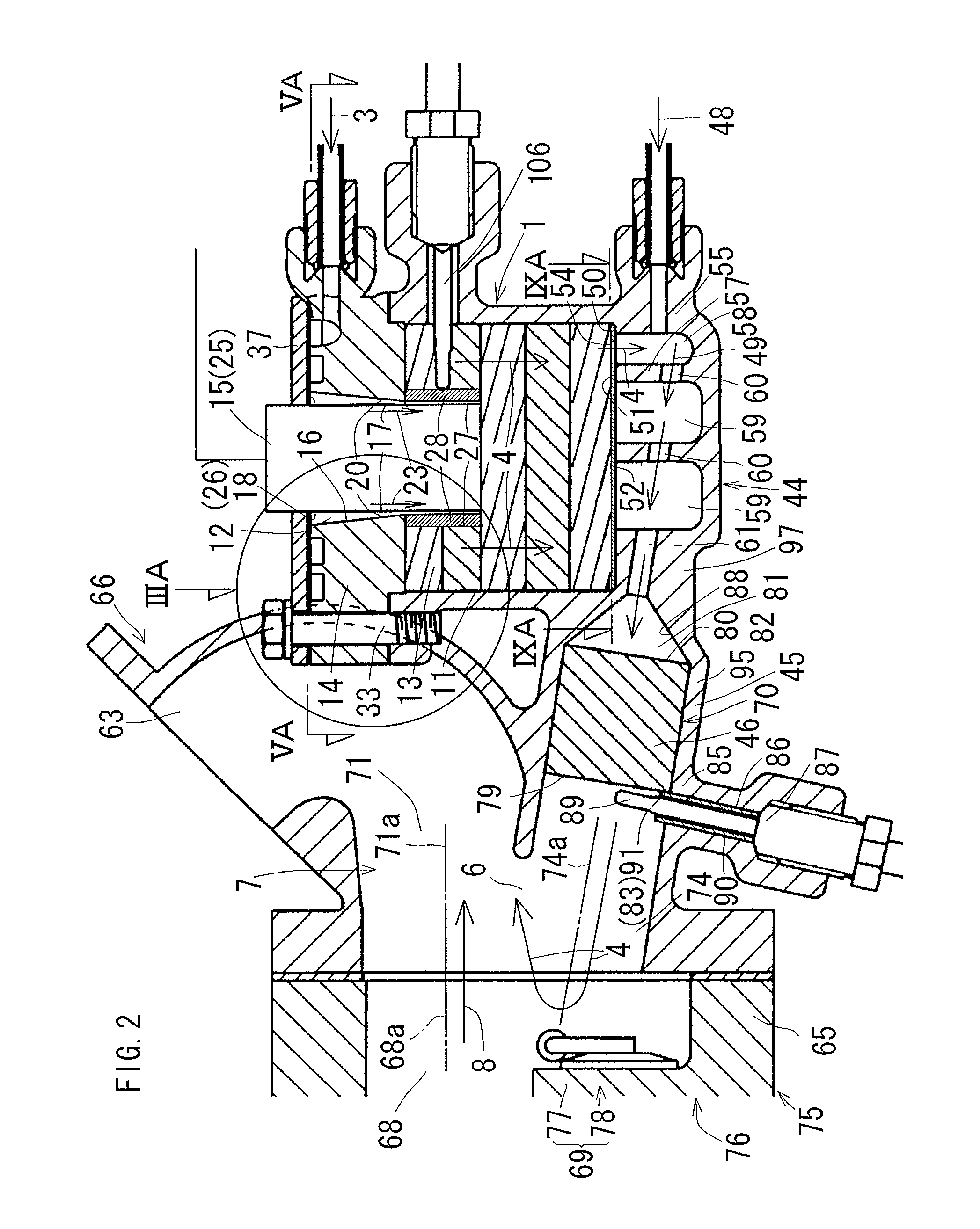
[0022]As illustrated in FIGS. 3(A) and 3(B), FIGS. 4(A) and 4(B), and FIG. 7, the heat-dissipating outer peripheral surface 26 of the heater 25 is exposed to the air-fuel mixing chamber 12 by using the heater 25 as the core member 15 and, when the combustible gas 4 starts being generated, the heat is directly radiated from the heat-dissipating outer peripheral surface 26 of the heater 25 to the air-fuel mixing chamber 12. Accordingly, the generation of the combustible gas 4 can be smoothly started because the heat of the heater 25 is rapidly transferred to the air-fuel mixing chamber 12 and the air-fuel mixture gas 23 is rapidly formed.
[0023]Effect The size of a combustible gas generator can be reduced.
[0024]The size of the combustible gas generator 1 can be reduced because an intervening substance does not exist between the heater 25 and the air-fuel mixing chamber 12, as illustrated in FIGS. 3(A) and 3(B), FIGS. 4 (A) and 4(B), and FIG. 7.
[0025]Effect The generation of a combustible gas can be efficiently performed.

Problems solved by technology

Problem There is the case in which the generation of a combustible gas is not smoothly started.
Accordingly, it is difficult for the heat of the heater to be transferred to the air-fuel mixing chamber and the generation of the combustible gas may not be smoothly started because the formation of an air-fuel mixture gas is delayed.
Problem There is the case in which the size of the combustible gas generator may be increased.

Method used


Image

  • Exhaust gas treatment device for diesel engine
  • Exhaust gas treatment device for diesel engine
  • Exhaust gas treatment device for diesel engine

Examples


Embodiment Construction

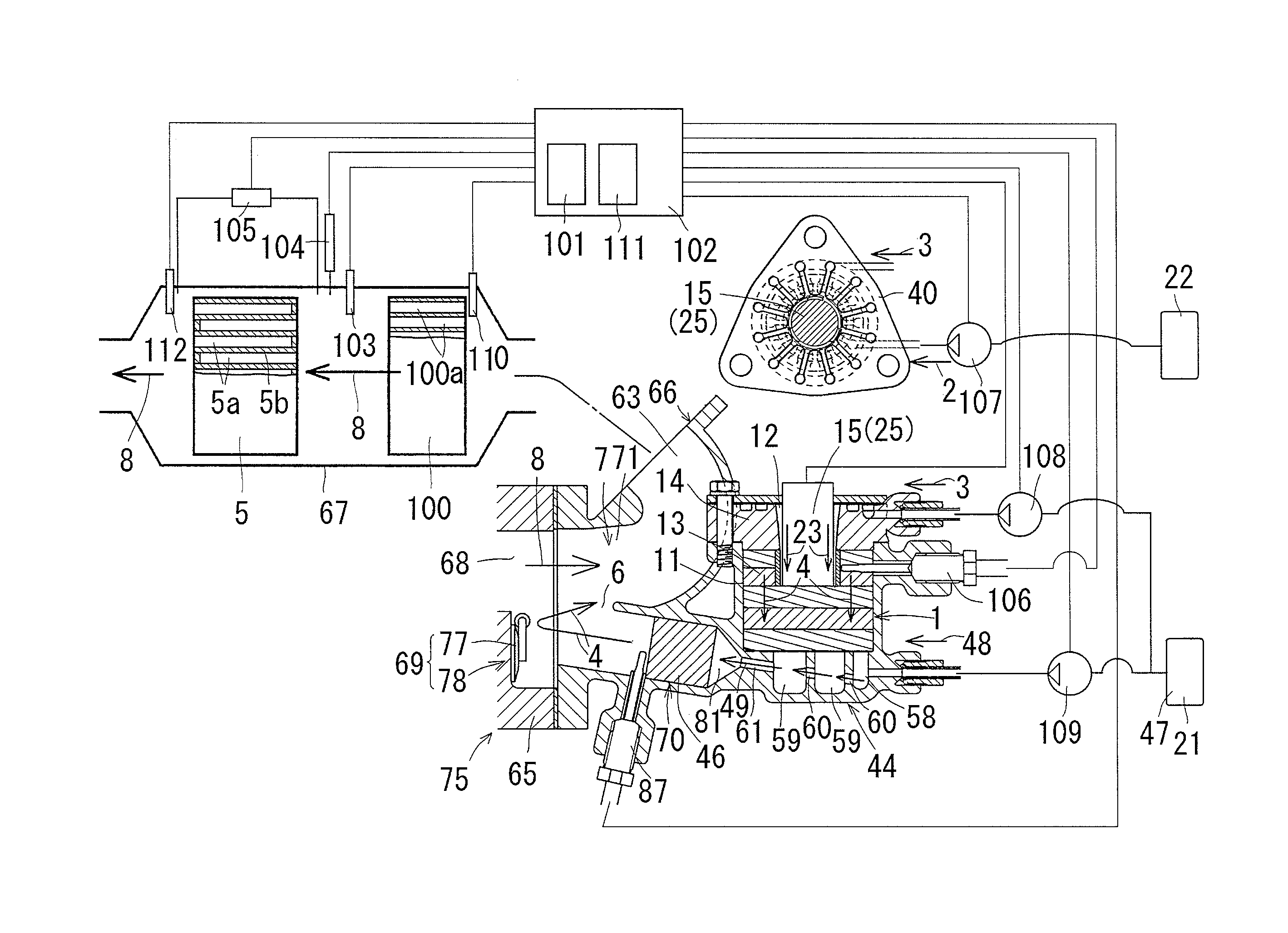
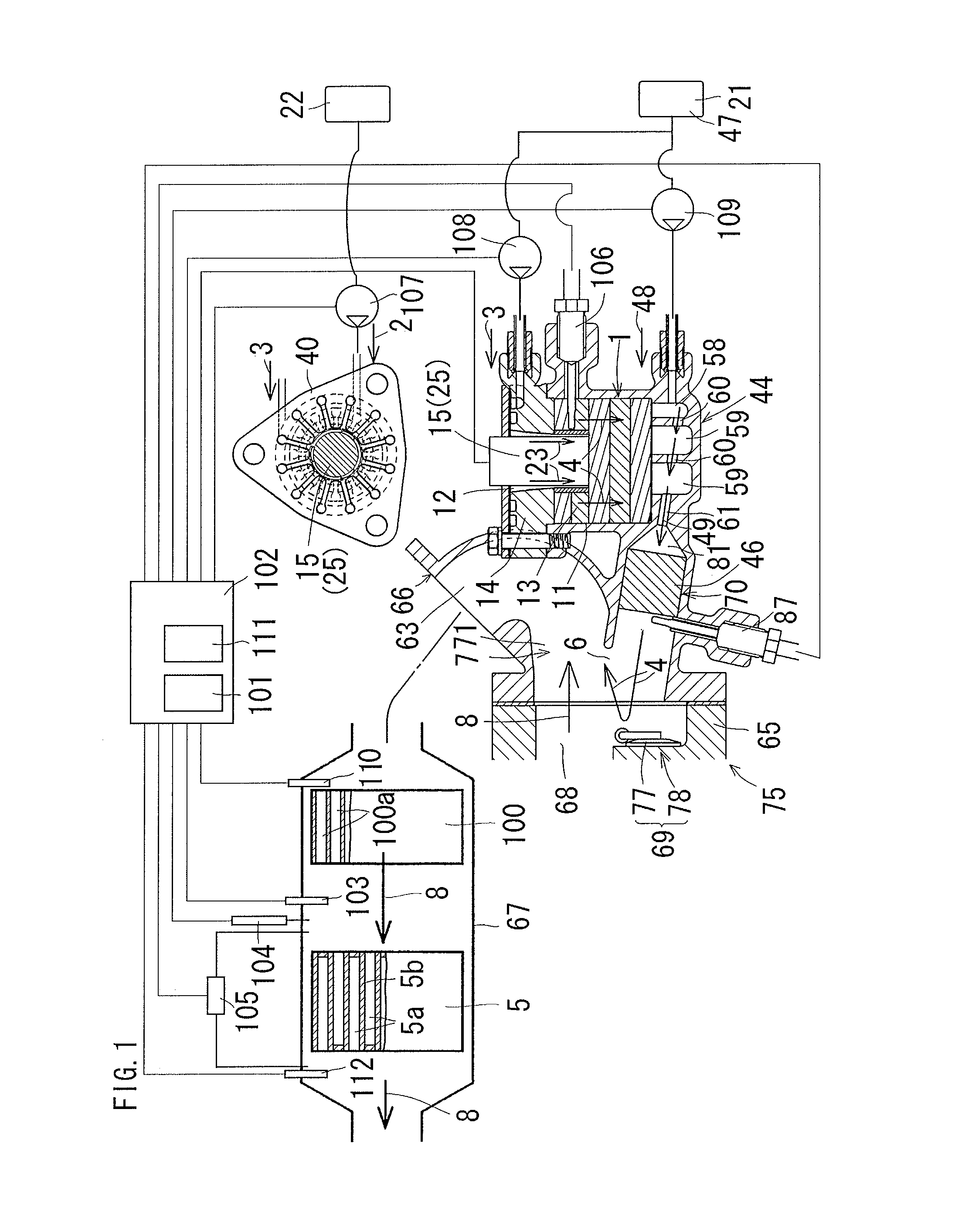
[0115]FIGS. 1 to 15 are diagrams illustrating an exhaust gas treatment device for a diesel engine according to an embodiment of the present invention. In the present embodiment, an exhaust gas treatment device for a vertical (upright type) multi-cylinder diesel engine is described.

[0116]An outline of the exhaust gas treatment device is as follows.

[0117]As shown in FIGS. 11 to 13, an exhaust manifold 113 is mounted on the lateral side of the cylinder head 112, a super charger 75 is mounted over the exhaust manifold 113, and a DPF casing 67 is coupled to the exhaust turbine 76 of the super charger 75 through an exhaust pipe 66. A combustible gas generator 1 is installed in the exhaust pipe 66.

[0118]As shown in FIG. 1, a combustible gas 4 is generated by the combustible gas generator 1, the combustible gas 4 is discharged from a combustible gas discharge port 6 to an exhaust passage 7 in the upper stream of a DPF 5, the combustible gas 4 is burnt by oxygen within the exhaust gas 8, a t...


PUM


Abstract

An exhaust gas treatment device for a diesel engine capable of starting the generation of a combustible gas is provided. The device includes a combustible gas generator. A core member is fitted in the center portion of an annular wall to form an air-fuel mixing chamber between the inner peripheral surface of the annular wall and the outer peripheral surface of the core member. An air-fuel mixture gas in the air-fuel mixing chamber is adapted to be supplied from the end of the air-fuel mixing chamber to a combustible gas generating catalyst to a portion near the center thereof. A heater is used as the core member. The heat dissipating outer peripheral surface of the heater is exposed to the air-fuel mixing chamber. Heat is dissipated directly from the heat dissipating outer peripheral surface of the heater to the air-fuel mixing chamber when starting the generation of the combustible gas.

Description

CROSS-REFERENCE TO RELATED APPLICATION[0001]This application is a Section 371 of International Application No. PCT / JP2011 / 056177, filed Mar. 16, 2011, which was published in the Japanese language on Oct. 13, 2011, under International Publication No. WO 2011 / 125438 A1, and the disclosure of which is incorporated herein by reference.TECHNICAL FIELD[0002]The present invention relates to an exhaust gas treatment device for a diesel engine and, more particularly, to an exhaust gas treatment device for a diesel engine, which can smoothly start the generation of a combustible gas and also reduce the size of a combustible gas generator.[0003]From among the terms of this specification and claims, a DPF is an abbreviation of a diesel particulate filter, and a PM is an abbreviation of a particulate matter included in an exhaust gas, and a DOC means a diesel oxidization catalyst.BACKGROUND ART[0004]There is a conventional device in which a combustible gas is generated by a combustible gas gener...

Claims


Application Information

Patent Timeline
Patent Type & Authority Patents(United States)
IPC IPC(8): F01N3/00
CPCF02M27/02B01D53/944F01N3/025F01N3/035F01N3/105F01N3/36F01N9/002F01N13/0097F01N2240/14F01N2610/08F01N2610/10F02B3/06F23G7/065Y02T10/16Y02T10/47Y02E20/12Y02T10/12Y02T10/40F01N3/02F01N3/023F01N3/30
Inventor ONISHI, TAKASHINAITO, KEITANAKAHIRA, TOSHIOTAKEMOTO, YOSHIKAZU
Owner KUBOTA CORP
Why Eureka
Eureka Blog
Learn More