Diaphragm member and diaphragm valve provided with diaphragm member

a technology of diaphragm and diaphragm valve, which is applied in the direction of diaphragm valves, valve housings, instruments, etc., can solve the problems of low melt flow rate of ptfe, short life of the diaphragm formed by cutting in this way, and inability to form a high-quality diaphragm

Active Publication Date: 2020-02-13
ADVANCE DENKI KOUGYOU
View PDF0 Cites 1 Cited by
  • Summary
  • Abstract
  • Description
  • Claims
  • Application Information

AI Technical Summary

Benefits of technology

[0021]It is therefore an object of the present invention to provide a diaphragm member which is constructed as a diaphragm construction applying laser welding to coupling with the central hole portion of the diaphragm of the valve body, even if the diaphragm is as thin as a film by selecti

Problems solved by technology

Herein, in case PTFE is used as a forming material of the diaphragm, it is impossible to form a diaphragm with high quality by injection molding or extrusion molding, because PTFE is low in its melt flow rate.
The diaphragm of PFA formed by cutting in this way has short life.
Herein, in case PFA is used as the forming material of a diaphragm and the diaphragm is formed by molding a thick curved displacement portion by injection molding with PFA and then cutting the same, crystallization of the curved displacement portion is not uniformly caused.
Accordingly, the interface of the curved displacement portion becomes a starting point of destruction and life of the curved displacement portion becomes

Method used


Image

  • Diaphragm member and diaphragm valve provided with diaphragm member
  • Diaphragm member and diaphragm valve provided with diaphragm member
  • Diaphragm member and diaphragm valve provided with diaphragm member

Examples


first embodiment

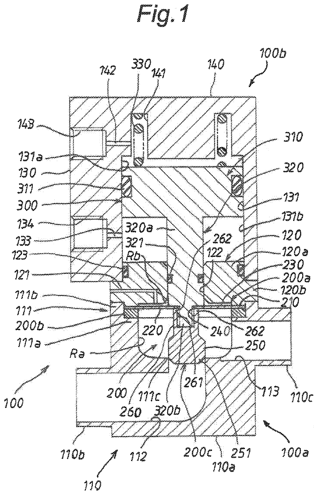
[0094]FIG. 1 illustrates a first embodiment of a diaphragm valve to which the present invention is applied. As the diaphragm valve, an air operated diaphragm valve applied to a semiconductor manufacturing apparatus for manufacturing semiconductor elements is adopted.

[0095]The diaphragm valve is interposed in a piping system of the semiconductor manufacturing apparatus, and is configured or constructed to flow a liquid flowing in the piping system from an upstream side to a downstream side of the piping system. In the first embodiment, the liquid is a liquid such as a high-purity chemical solution or liquid, ultrapure water or the like. The liquid is supplied from a liquid supply source to the piping system in the semiconductor manufacturing apparatus. The liquid is required to be clean from the nature as the semiconductor manufacturing apparatus.

[0096]As illustrated in FIG. 1, the diaphragm valve includes a cylindrical housing 100, a diaphragm member 200 assembled to the cylindrical...

second embodiment

[0209]FIG. 6 illustrates a main portion of a second embodiment of the present invention. According to the second embodiment, in an air-operated diaphragm valve, a diaphragm member formed by laser welding an annular body 200b for reinforcement to an outer peripheral portion 210 of a diaphragm 200a from its upper surface side is adopted instead of the diaphragm member 200 described in the first embodiment. In addition, the diaphragm member according to the second embodiment is also denoted by the reference numeral 200 as in the first embodiment.

[0210]The diaphragm member 200 is constructed by the diaphragm 200a, the annular body 200b for reinforcement, and a valve body 200c as in the first embodiment.

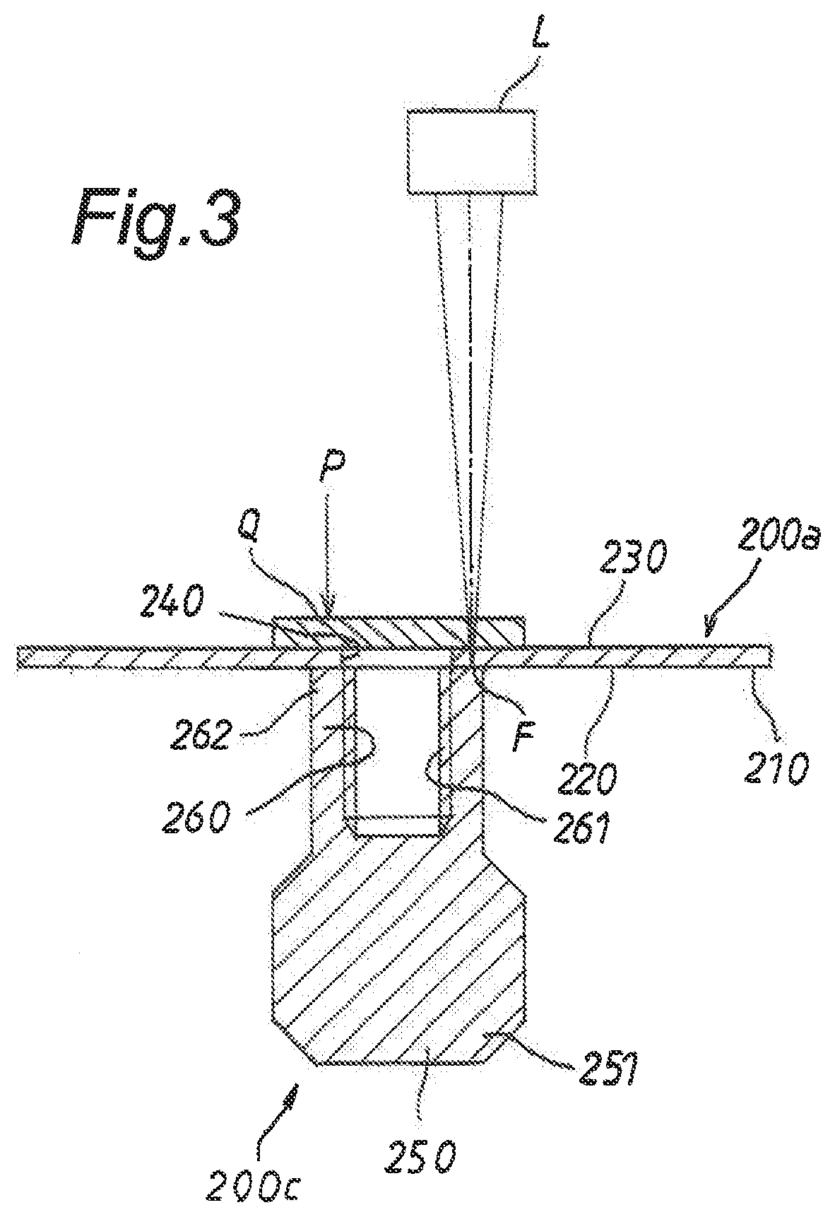
[0211]Also in the second embodiment, the valve body 200c is laser welded at an open end portion 262 of a neck portion 260 to a central hole portion 240 of the diaphragm 200a as in the first embodiment. Unlike the first embodiment, the annular body 200b for reinforcement is laser welded to...

third embodiment

[0222]FIG. 8 illustrates a third embodiment of a diaphragm valve to which the present invention is applied. In the third embodiment, as a diaphragm valve, an electromagnetically operated diaphragm valve is adopted, differing from the air-operated diaphragm valve described in the first embodiment.

[0223]As illustrated in FIG. 8, the electromagnetically operated diaphragm valve includes a cylindrical housing, the diaphragm member 200 described in the first embodiment, and an electromagnetically operated driving mechanism 400 and is constructed as a solenoid valve of a normally closed type. In addition, in the third embodiment, the cylindrical housing is also denoted by the reference numeral 100 as in the first embodiment. Hereinafter, the electromagnetically operated driving mechanism 400 will be also referred to as the driving mechanism 400.

[0224]The cylindrical housing 100 according to the third embodiment is constructed by a lower housing member 100c and an upper housing member 100d...


PUM

PropertyMeasurementUnit
Thicknessaaaaaaaaaa
Thicknessaaaaaaaaaa
Shapeaaaaaaaaaa

Abstract

A diaphragm member includes a film-shaped diaphragm made of PFA and a valve body which is laser welded to a central hole portion of the diaphragm.

Description

BACKGROUND OF THE INVENTIONField of the Invention[0001]The present invention relates to a diaphragm member suitable for use in a diaphragm valve which causes a liquid such as a high-purity chemical liquid or ultrapure water to flow in a semiconductor manufacturing apparatus, and a diaphragm valve provided or equipped with the diaphragm member.Description of the Related Art[0002]Conventionally, a diaphragm valve of this type includes a housing, a diaphragm supported axially displaceably in a curved shape in the housing, and a driving mechanism assembled in the housing to drive the diaphragm so as to axially displace the diaphragm in the curved shape.[0003]In case the diaphragm valve having the structure described above is used in a semiconductor manufacturing apparatus, it is desirable to use fluorine resin excellent in chemical resistance such as acid resistance, alkali resistance or the like, as a forming material of the diaphragm in the diaphragm valve. This is because highly corr...

Claims


Application Information

Patent Timeline
IPC IPC(8): F16K7/17F16K7/12G05D7/01F16J15/06F16J3/02B29C65/16
CPCF16K7/126G05D7/012F16J15/06F16K7/17B29C65/1635F16J3/02F16K41/12F16K7/123F16K7/12F16K51/02F16K7/18F16K27/0236F16K31/0644H01L21/67017B29C48/255B29C65/16B29L2031/755
Inventor MATSUZAWA, HIRONORIFUJIKAWA, NOBUYUKI
Owner ADVANCE DENKI KOUGYOU
Why Eureka
Try Eureka