LED light bar

a technology of led light and light rail, which is applied in the direction of light source semiconductor devices, transportation and packaging, lighting and heating apparatus, etc., can solve the problems of unsatisfactory heat dissipation, large weight, and heat dissipation of light source and waterproofness, so as to reduce heat resistance and shorten heat-conducting paths , the effect of improving efficiency

Inactive Publication Date: 2014-07-01
SHANGHAI SANSI ELECTRONICS ENG +2
View PDF5 Cites 4 Cited by
  • Summary
  • Abstract
  • Description
  • Claims
  • Application Information

AI Technical Summary

Benefits of technology

[0007]In order to solve problems mentioned above, the present invention provides a LED light bar having a good performance in dissipating heats, dampproofness and waterproofness, which is simply manufactured and used.
[0015]The LED light bar of the present invention has no circuit board for welding LED light sources and adopts metal electricity-conducting plates of highly heat-conducting which reduces the heat resistance and shortens heat-conducting paths to produce higher efficiency and better performance in dissipating heats. Moreover, the electrical electricity-conducting layer is provided in the inner part of the non-electricity-conducting light source mounting base. Thus results of effective dampproofness and waterproofness are realized without adopting other materials for sealing, and are free from limitations of service time and severe service environment. The light source mounting base and the central metal electricity-conducting plates are formed into a whole through plastic injection molding, which contributes to mass production and installation and effectively improves productive efficiency of lamps.

Problems solved by technology

When a LED is used as a light source of a lighting lamp, main problems to be solved in designing are dissipating heats of the light source and waterproofness of the light lamps.
However, such a structure condenses heats in a sealed space and causes unsatisfied heat dissipation results.
The heavy structure also leads to a big weight and a big cost in materials of the whole lamp.
Besides, the conventional light source is installed integrally, which leads to great inconvenience in installing and maintaining, a low productive efficiency, a low level in scale and standardization.

Method used


Image

  • LED light bar
  • LED light bar
  • LED light bar

Examples


Embodiment Construction

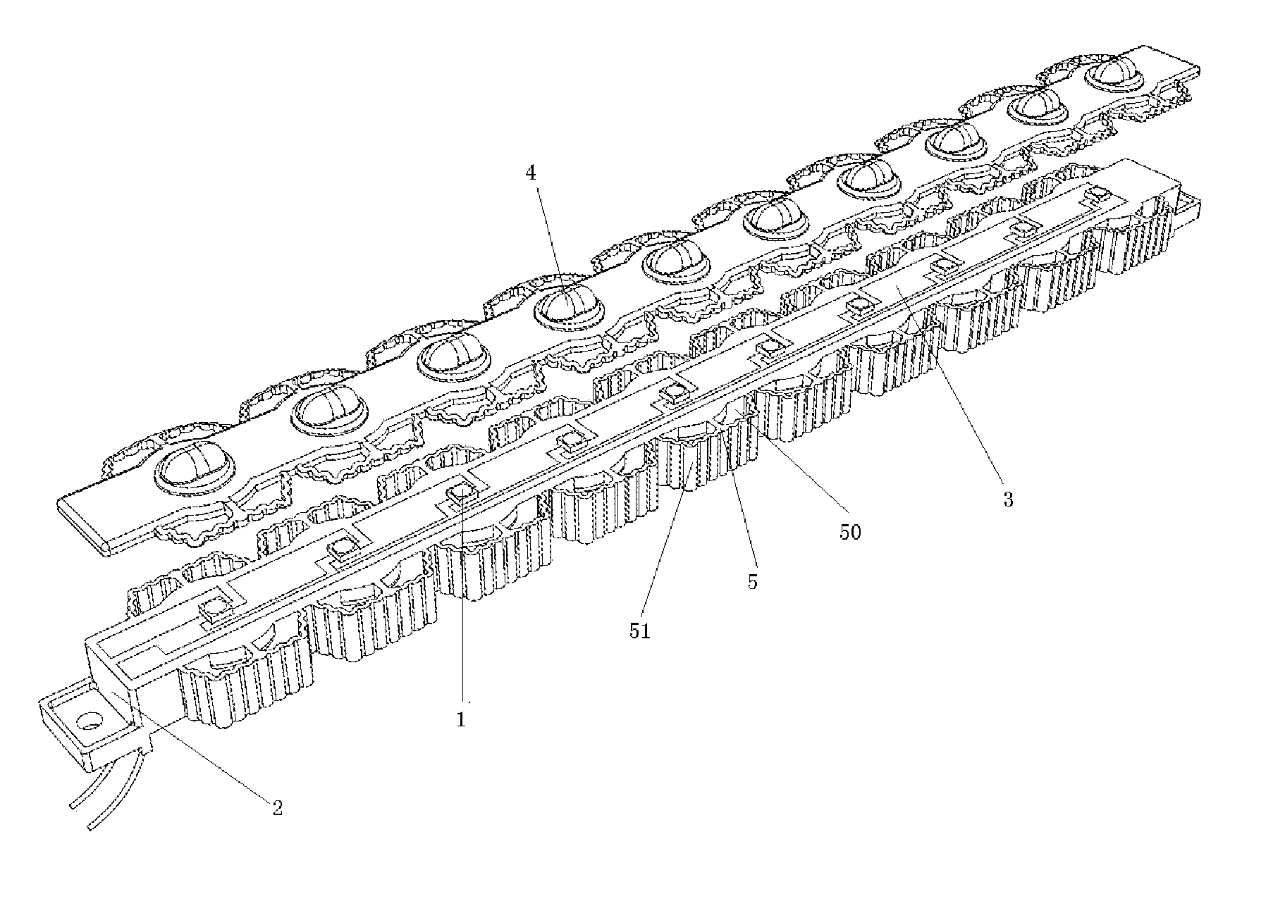
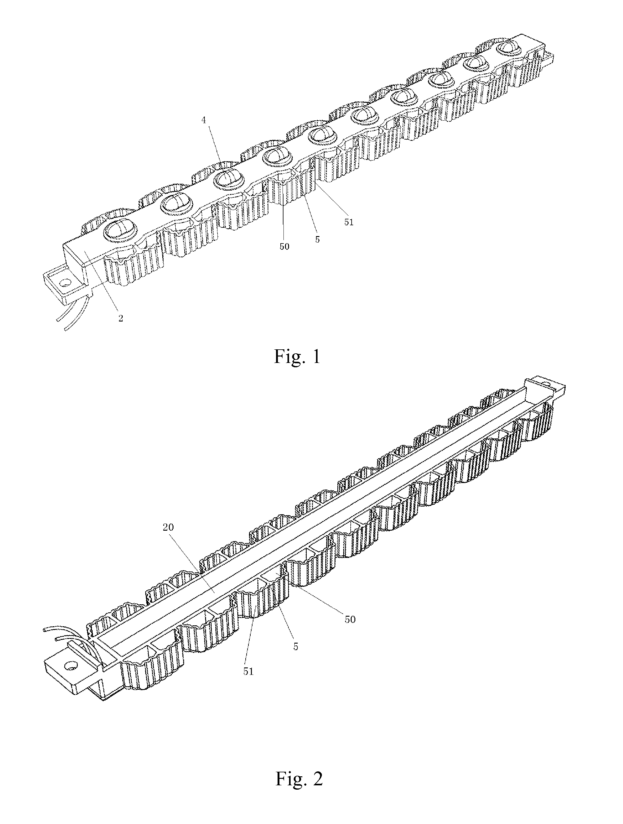
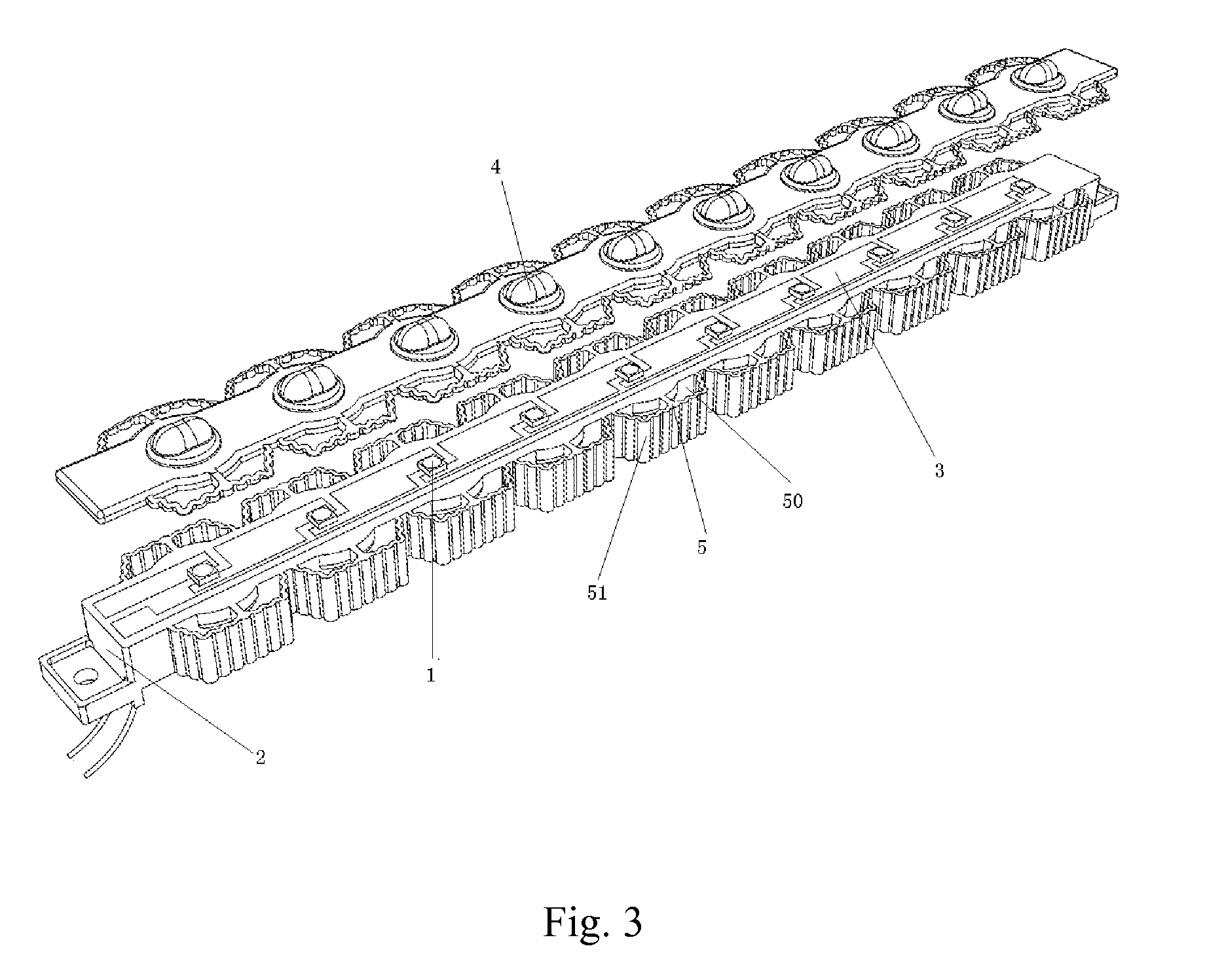
[0020]In FIG. 1, FIG. 2 and FIG. 3, according to a preferred embodiment of the present invention, a LED light bar is illustrated which comprising several LED light sources 1 and a bar light source mounting base 2. The light source mounting base 2 is made of insulating and heat-conducting materials. An electrical layer having several metal electricity-conducting plates is embedded in an inner part of the light source mounting base 2, wherein copper plates 3 of the metal electricity-conducting plates in the preferred embodiment have high heat-conducting coefficients. The light source mounting base 2 and the electrical layer comprising the copper plates 3 are formed into a whole through plastic injection molding. The several copper plates 3 are insulated connected with each other. Pins of positive electrodes and negative electrodes of the LED light sources 1 bridge among the copper plates connected with each other so as to form an electrical electricity-conducting circuit with the copp...


PUM


Abstract

A LED light bar includes several LED light sources and a bar light source mounting base. The light source mounting base is made of an insulating and heat-conducting material. An electrical layer having several metal electricity-conducting plates is embedded in an inner part of the light source mounting base. The LED light sources are welded on the metal electricity-conducting plates to form an electrical electricity-conducting circuit. lighting sides of the LED light sources are exposed on a surface of the light source mounting base. The light source mounting base and the metal electricity-conducting plates are formed into a whole. Each LED light source is covered by lenses.

Description

BACKGROUND OF THE PRESENT INVENTION[0001]1. Field of Invention[0002]The present invention relates to a field of LED lighting, and more particularly to a light bar of a LED lighting lamp having a high heat dissipating efficiency and a high protecting level.[0003]2. Description of Related Arts[0004]When a LED is used as a light source of a lighting lamp, main problems to be solved in designing are dissipating heats of the light source and waterproofness of the light lamps. For example, a conventional road lamp commonly has a front mask and a back cover to satisfy a requirement of dampproofness and waterproofness. However, such a structure condenses heats in a sealed space and causes unsatisfied heat dissipation results. The heavy structure also leads to a big weight and a big cost in materials of the whole lamp.[0005]Besides, the conventional light source is installed integrally, which leads to great inconvenience in installing and maintaining, a low productive efficiency, a low level...

Claims


Application Information

Patent Timeline
Patent Type & Authority Patents(United States)
IPC IPC(8): F21V29/00
CPCF21V15/011F21V31/00F21Y2103/003F21V29/244F21S4/008F21Y2101/02H05K3/202H05K2201/10106F21V29/2206F21V5/007F21V29/507F21V29/74F21V29/87F21S4/28F21Y2103/10F21Y2115/10
Inventor CHEN, MINGQIU, YONGHONGGUO, LIANGWU, JIYE
Owner SHANGHAI SANSI ELECTRONICS ENG
Why Eureka
Try Eureka