
Axial-centrifugal compressor having system for controlling play

Active Publication Date: 2014-07-01
SN DETUDE & DE CONSTR DE MOTEURS DAVIATION S N E C M A
View PDF16 Cites 0 Cited by
  • Summary
  • Abstract
  • Description
  • Claims
  • Application Information

AI Technical Summary

Benefits of technology

The device described in this patent allows for adjustable axial play without affecting radial play. It is especially useful at cruising speeds, where the device is not actively adjusting, to achieve significant savings. The device uses a heat exchanger to cool the rotor, resulting in contractions of the rotor. The heat exchanger consists of a section of the stator passing through an outer cavity of the second arm, making it simple and efficient.

Problems solved by technology

The use of conventional ventilation devices would not give good results since the axial play would be controlled at the same time as the radial play of the first portion of the compressor, which would be incompatible for obtaining satisfactory results.

Method used


Image

  • Axial-centrifugal compressor having system for controlling play
  • Axial-centrifugal compressor having system for controlling play
  • Axial-centrifugal compressor having system for controlling play

Examples


Embodiment Construction

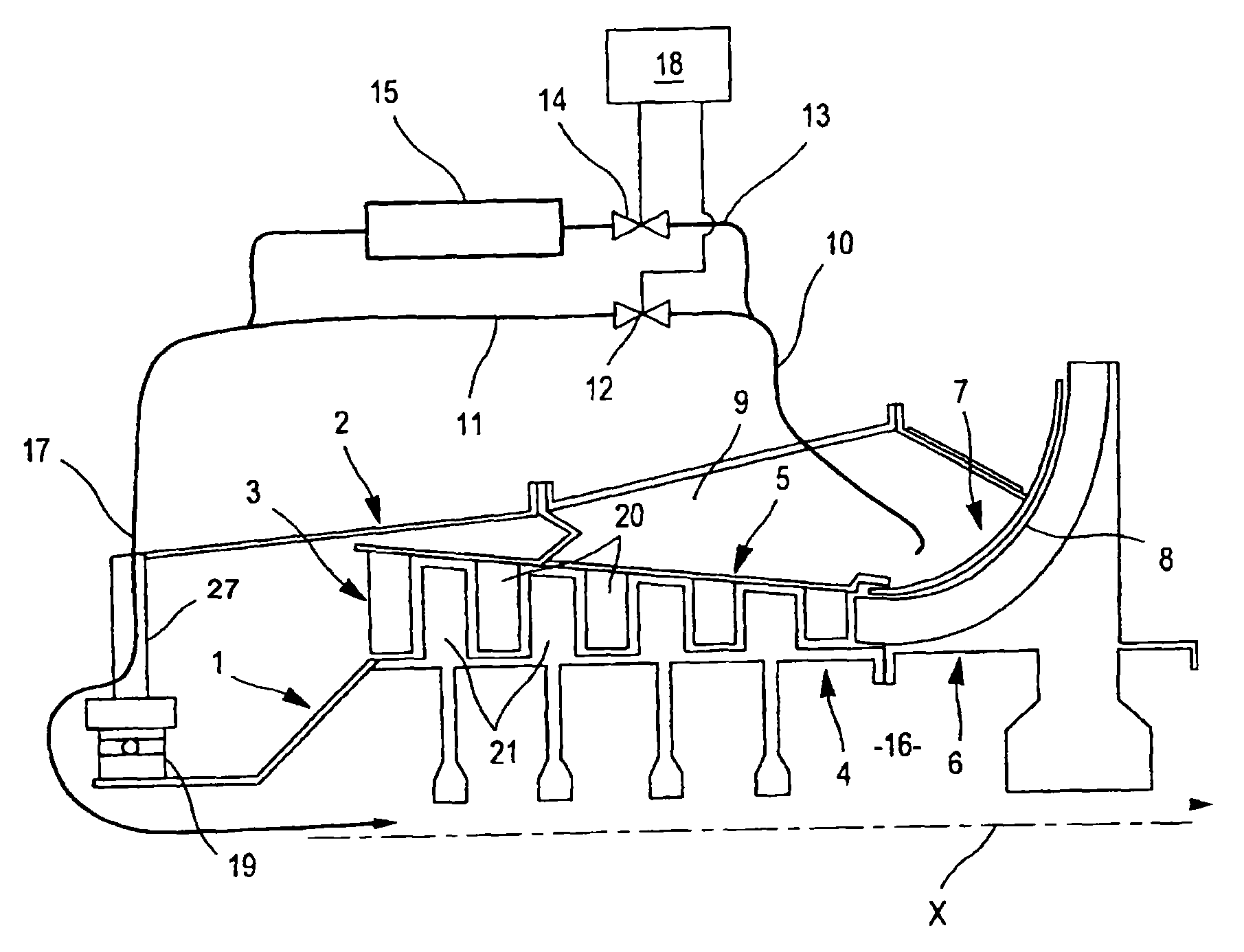
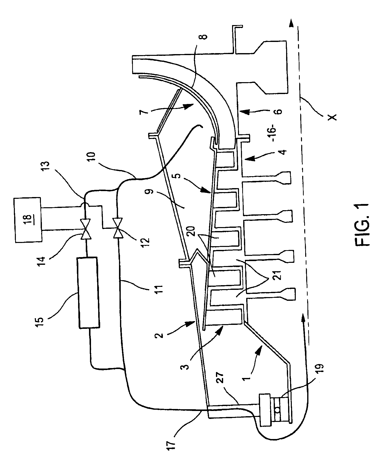
[0017]The axial-centrifugal compressor comprises a rotor 1 and a stator 2 separated by a vein 3 for gas flow. The rotor 1 and the stator 2 each have an substantially cylindrical axial portion, 4 or 5 respectively, and then a spread-out portion, 6 or 7 respectively spread out. The portion 6 of the rotor 1 is the impeller. It is the axial play 8 between these spread-out portions 6 and 7 which should be adjusted. Its value is typically of a few tens of millimeters at rest (0.7 or 0.8 mm for example).

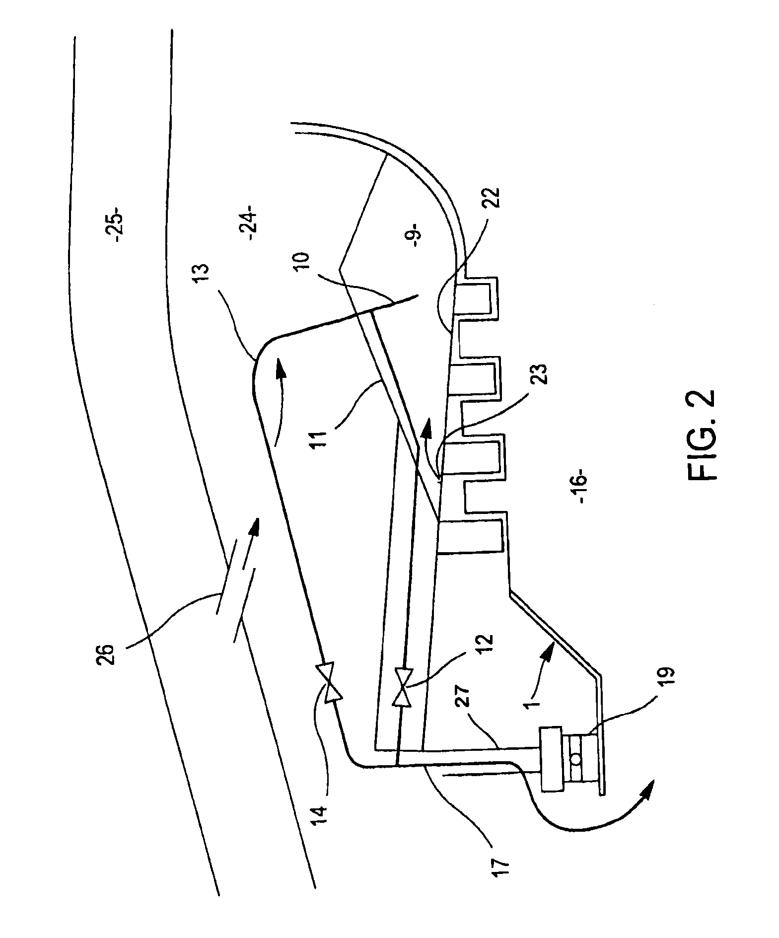
[0018]The stator 2 includes cavities 9 around the vein 3. A conduit 10 opens out into one of them and draws a flow of its gas contents. It is then divided into a first arm 11 equipped with a first valve 12 and into a second arm 13 equipped with a second valve 14 and with a heat exchanger 15. The arms 11 and 13 then join together and their flows end up in a cavity 16 of the rotor 1 through a common conduit 17. This however is not necessary, the flows may remain separate up to the cavity 16. ...


PUM


Abstract

In an axial-centrifugal compressor, the rotor of which includes an impeller, axial play is controlled by a special air ventilation to the rotor, by a circuit including two parallel arms, flow rates of which are both controlled by respective veins, and moreover the temperature in one of them is changed by a heat exchanger. The ventilation air is thus controlled, both in terms of temperature and flow rate.

Description

BACKGROUND OF THE INVENTION[0001]The subject of this invention is an axial-centrifugal compressor having a system for controlling axial play.[0002]An axial-centrifugal compressor comprises a first conventional portion, where the rotor and the stator are cylindrical and concentric around the axis line of the compressor, and then a portion where they spread out in a radial direction so that the corresponding portion of the rotor, called an impeller extends beyond the stator along the axis line. One of its advantages is to reduce the bulkiness of the machine in the direction of the axis and to produce more compact and more lightweight machines.[0003]The yield of the compressors and of the machines to which they may be integrated greatly depends on the plays existing between the rotor and the stator and which are responsible for energy losses in the flow of the gases. It is conventional to adjust these plays by ventilation of a gas at the intended temperature and flow rate in order to p...

Claims


Application Information

Patent Timeline
IPC IPC(8): F01D25/14
CPCF04D29/584F01D9/065F01D11/24F02C6/08F02C7/185F04D29/164F05D2210/42Y02T50/60
Inventor BEHAGHEL, LAURENT DONATIENFONTANEL, EDDY STEPHANE JOELPEGOUET, BENJAMIN PHILIPPE PIERRE
Owner SN DETUDE & DE CONSTR DE MOTEURS DAVIATION S N E C M A
Features
  • Generate Ideas
  • Intellectual Property
  • Life Sciences
  • Materials
  • Tech Scout
  • Unparalleled Data Quality
  • Higher Quality Content
  • 60% Fewer Hallucinations
Learn More