Calcaneus step plate

a calcaneus and step plate technology, applied in the field of new bone plate for calcaneal fracture treatment, can solve the problems of limited plate number of holes, inability to mold significant, and inability to meet clinical and technical requirements

Active Publication Date: 2014-07-01
ARTHREX
View PDF14 Cites 50 Cited by
  • Summary
  • Abstract
  • Description
  • Claims
  • Application Information

AI Technical Summary

Benefits of technology

[0008]The arc-shaped compression hole provides a unique sliding mechanism that imparts compression on the counter cortex and helps with the sliding osteotomy as the tendons tend to pull back. The center sliding mechanism of the step plate of the invention also allows tilting of the compression screw (with both sliding and rotation of the compression screw) to achieve compression on the counter cortex.

Problems solved by technology

Although open reduction and internal fixation of intra-articular calcaneal fractures has become a standard surgical procedure with relatively low complication rate, there are still problems associated with this technique, primarily because of the complicated physical arrangement of the articular surfaces of the calcaneus (calcaneal bone).
Clinical and technical problems can also occur due to the thickness and the stiffness of the plates, in particular superficial necrosis of the surgical wounds and peroneal tendonitis.
These problems are related to the traction onto the skin flap during surgery and to the thickness of the plates that may cause ischemic problems to the skin and impingement of the peroneal tendons.
In addition, most plates have a limited number of holes and do not allow for significant molding because of their thickness.
Sometimes, this can lead to insufficient grip of the screws and therefore insufficient mechanical resistance of the implant.
In those circumstances, early movement to prevent joint stiffness and enhance fractured soft tissue healing is not possible.

Method used


Image

  • Calcaneus step plate
  • Calcaneus step plate
  • Calcaneus step plate

Examples


Embodiment Construction

[0013]In the following detailed description, reference is made to various specific embodiments in which the invention may be practiced. These embodiments are described with sufficient detail to enable those skilled in the art to practice the invention, and it is to be understood that other embodiments may be employed, and that structural and logical changes may be made without departing from the spirit or scope of the present invention.

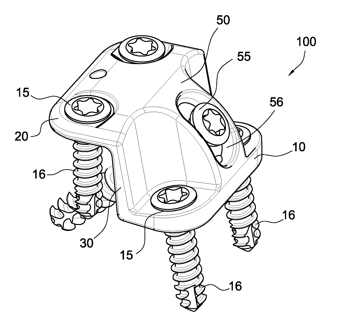
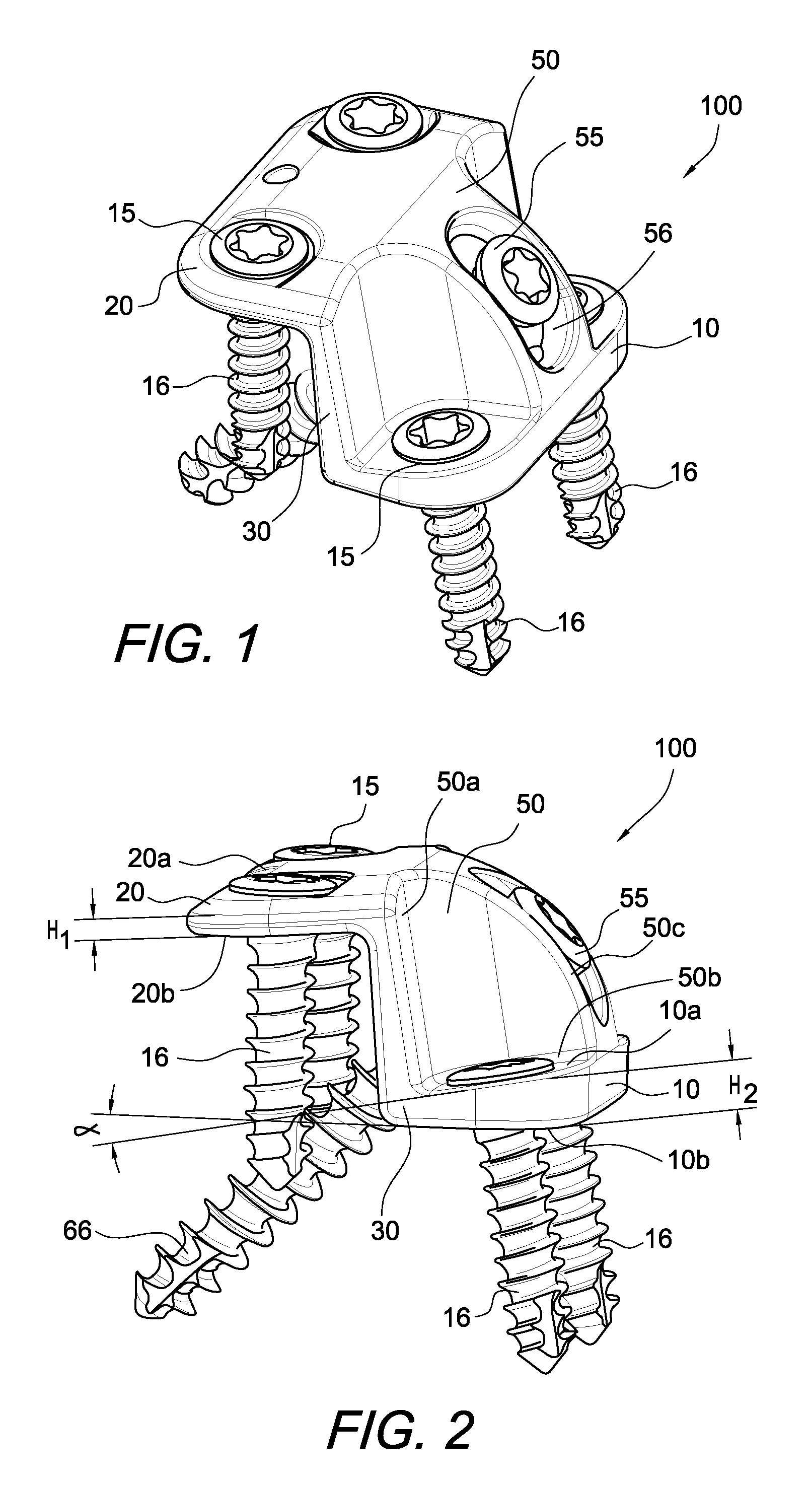
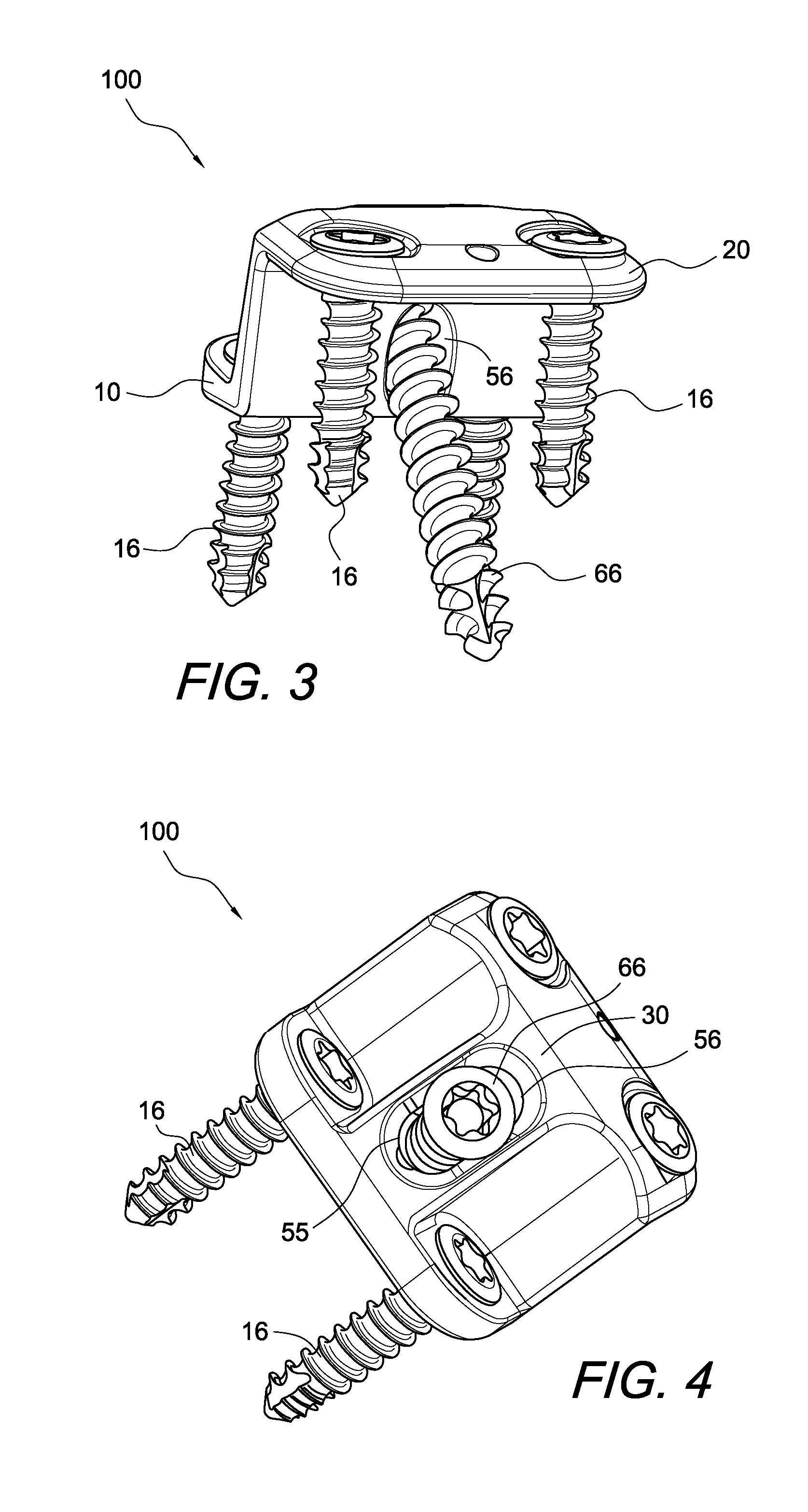
[0014]The present invention provides a bone plate (a correction osteotomy plate) that may be used in conjunction with various calcaneal repair procedures.

[0015]The calcaneus step plate of the present invention has a stepped configuration and is provided with two vertically-spaced plate sections connected by an intermediate wall having a center sliding mechanism. The two vertically-spaced plate sections are about parallel to each other and the intermediate wall extends about perpendicular to them. The two vertically-spaced plate sections extend on oppo...


PUM


Abstract

A calcaneus plate provided with two vertically-spaced plate sections, with corner-located screw holes. An intermediate wall connects the plate sections. An arcuate protrusion extends from the intermediate wall and contains an internal sliding mechanism for a compression screw. The sliding mechanism includes an arc-shaped compression hole with an elongated opening that includes a ridge upon with the compression screw head can slide.

Description

CROSS-REFERENCE TO RELATED APPLICATIONS[0001]This application claims the benefit of U.S. Provisional Application No. 61 / 353,590, filed Jun. 10, 2010, the entire disclosure of which is incorporated by reference herein.FIELD OF THE INVENTION[0002]The present invention relates to a novel bone plate for calcaneal fracture treatment.BACKGROUND OF THE INVENTION[0003]Calcaneal fractures are typically caused by a high-velocity impact to the heel (for example, a fall from a height of at least two meters or an impact as a result of a motor vehicle accident). Calcaneal fractures may be extra or intra-articular.[0004]One method currently used for treatment of calcaneal fractures is surgical treatment with open reduction and internal fixation, to restore the articular surface of the calcaneus and to obtain an anatomic reconstruction (height and width of the calcaneus). Although open reduction and internal fixation of intra-articular calcaneal fractures has become a standard surgical procedure wi...

Claims


Application Information

Patent Timeline
Patent Type & Authority Patents(United States)
IPC IPC(8): A61B17/80
CPCA61B17/8061A61B17/15A61B17/8014A61B2019/461A61B2090/061
Inventor MICHEL, GERLINDEVAN DIJK, C. NIEK
Owner ARTHREX
Why Eureka
Try Eureka