
Magnetoresistive sensor with funnel-shaped free layer, magnetic head, head gimbal assembly, and disk drive unit with the same

a magnetoresistive sensor and free layer technology, applied in the direction of instruments, record information storage, head support, etc., can solve the problems of difficult to achieve high read sensitivity, influence the working performance of the head seriously, and low read sensitivity, so as to improve the height control performance, improve the esd performance, and reduce the noise of popcorn

Inactive Publication Date: 2014-07-01
SAE MAGNETICS (HK) LTD +1
View PDF5 Cites 5 Cited by
  • Summary
  • Abstract
  • Description
  • Claims
  • Application Information

AI Technical Summary

Benefits of technology

The design enhances lapping efficiency, stabilizes the free layer domain, reduces thermal noise, and improves read performance and electro-static discharge resistance, resulting in a more reliable and sensitive MR sensor.

Problems solved by technology

However, big thermal noises and low read sensitivity problems always exist in the above-mentioned MR sensors and influence their working performance seriously.
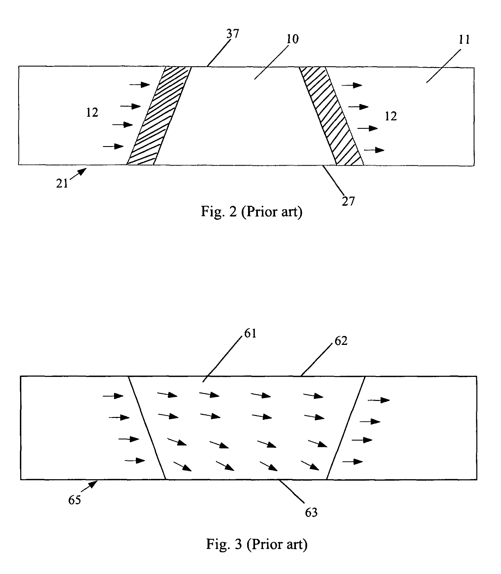
Unfortunately, because the bottom edge 27 facing ABS is still wider, a high read sensitivity is difficult to attain.
However, since the above-mentioned trapezoidal MR elements both has a wider bottom edge being lapped, so the lapping process of the bottom edge is difficult to control, and making the MR height difficult to control.
That is, the track width rests with the width of the MR element facing ABS, if the width of the MR element is too big, the track width is increased and, in turn, decreasing the data track density, which affects the read performance of the slider.
For example, if the sensor area is too small, the resistance area is decreased to cause reliability of the MR sensor become poorer.
At the same time, the current density crossing the sensor area is increased to bring electro-static discharge (ESD) problem.
In one word, it is a big problem to solve for existing MR sensor.

Method used


Image

  • Magnetoresistive sensor with funnel-shaped free layer, magnetic head, head gimbal assembly, and disk drive unit with the same
  • Magnetoresistive sensor with funnel-shaped free layer, magnetic head, head gimbal assembly, and disk drive unit with the same
  • Magnetoresistive sensor with funnel-shaped free layer, magnetic head, head gimbal assembly, and disk drive unit with the same

Examples


Embodiment Construction

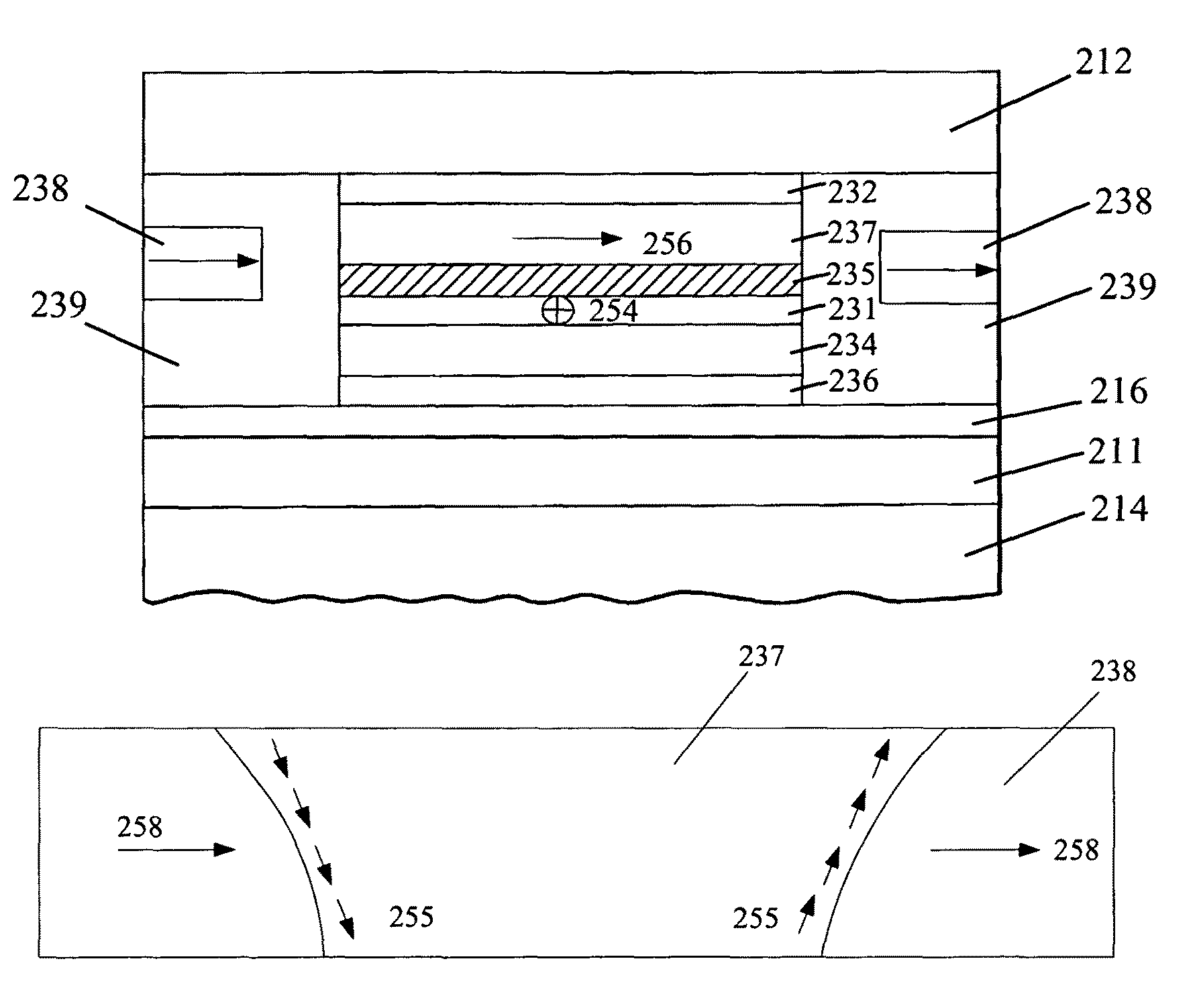
[0034]Various preferred embodiments of the invention will now be described with reference to the figures, wherein like reference numerals designate similar parts throughout the various views. As indicated above, the invention is directed to a MR sensor for a slider. The MR sensor has a MR element which comprises a funnel-shaped free layer, which has a first edge facing ABS and a second edge opposite the first edge, and the width of the first edge is narrower than that of the second edge. By such a design of a MR sensor of slider, a lapping area for the first edge facing ABS can be reduced and then a MR height of the MR sensor become easier to control, and simultaneously a big sensing area and a improved ESD performance can be attained and thermal noises can be reduced or even be eliminated.

[0035]Several example embodiments of a MR sensor for a magnetic head of a HGA of a disk drive unit will now be described. It is noted that the MR sensor may be implemented in any suitable HGA and / ...


PUM

PropertyMeasurementUnit
antiferromagneticaaaaaaaaaa
magnetoresistiveaaaaaaaaaa
widthaaaaaaaaaa

Abstract

An MR sensor includes a first shielding layer, a second shielding layer, an MR element formed therebetween, and a pair of hard magnet layers respectively placed on two sides of the MR element. The MR element includes an AFM layer formed on the first shielding layer, a pinned layer formed on the AFM layer and a free layer formed between the pinned layer and the second shielding layer. The free layer is funnel-shaped, which has a first edge facing an air bearing surface and a second edge opposite the first edge, and the first edge has a narrower width than that of the second edge. The MR sensor can improve MR height control performance, and improve the ESD performance and decrease the PCN and RTN and, in turn, get a more stable performance. The present invention also discloses a magnetic head, an HGA and a disk drive unit.

Description

FIELD OF THE INVENTION[0001]The present invention relates to information recording disk drive devices and, more particularly to a magnetoresistive (MR) sensor, a magnetic head, and a head gimbal assembly (HGA) and disk drive unit with the same.BACKGROUND OF THE INVENTION[0002]Hard disk drive incorporating rotating magnetic disks is commonly used for storing data in the magnetic media formed on the disk surfaces, and a movable slider including read sensors are generally used to read data from tracks on the disk surfaces.[0003]Presently, MR sensor is used as a kind of popular read sensor because of its better capability to read data from disk surface at a greater track and linear densities than traditional film inductive slider.[0004]Now, several types of MR sensors have been widely used by disk drive manufacturers in succession. One is anisotropic magnetoresistive (AMR) sensor, which makes the angle between the magnetization direction and the direction of sense current flowing throug...

Claims


Application Information

Patent Timeline
Patent Type & Authority Patents(United States)
IPC IPC(8): G11B5/39
CPCB82Y25/00G01R33/093G01R33/098G11B5/3932G11B5/398
Inventor LEUNG, CHIUMINGTANAKA, KOSUKESATO, KAZUKILEUNG, CHEUKWINGDING, JURENNI, RONGKWANGKWAN, WANYINLEE, MANKIT
Owner SAE MAGNETICS (HK) LTD
Learn More