Light-based communication for configuration of light-sensing peripherals

a technology of light-sensing peripherals and light-based communication, which is applied in the field of light-based communication, can solve the problems of complex process to make them all work properly, and the non-intuitive configuration process lacking simplicity, and achieves the effect of high strength

Inactive Publication Date: 2014-07-01
KONINK PHILIPS ELECTRONICS NV
View PDF10 Cites 10 Cited by
  • Summary
  • Abstract
  • Description
  • Claims
  • Application Information

AI Technical Summary

Benefits of technology

[0027]In accordance with an embodiment of the present invention, the central light-emitting unit emits light with embedded configuration data, instead of identifiers or codes, where different configuration data is continuously transmitted in different directions. This continuous transmission of configuration data may be triggered by, for example, user input, for instance by means of the user handling the central device or controlling the device by means of a remote control. The remote light-sensing device is equipped with means for receiving the transmitted light and processing means in order to process the embedded configuration data so that said remote light-sensing device may use the received configuration data, or received configuration data with the highest strength, to automatically configure itself. This embodiment of the present invention has the advantage that no further communication is necessary to acknowledge the received information nor is the conveying of further configuration data. Optionally the remote light-sensing device may send a configuration report back to the central unit after application of the spatial configuration.
[0028]In accordance with an embodiment of the present invention, the central light-emitting unit may comprise embedded identifiers in light, as well as means for receiving embedded identifiers in light, alternatively one of the two. The peripherals may also be arranged in the same way, i.e. equipped with a light source for transmitting identifiers as well as means for receiving identifiers embedded in light, alternatively one of the two. As an effect, each device may function as a peripheral device on one hand and / or a central device on the other. Hence, each particular device may determine its relative location with respect to another device and as such create a full positional map of all devices connected together via a wireless or wired network.
[0029]In accordance with an embodiment of the present invention, different data for different effects, such as light, music or other configuration data, is transmitted in different directions by the central light-emitting unit. A possible application could be a user wearing headphones containing the light-sensing device, in front of a 3D display screen. When the user moves relatively to the screen, different audio data will be received, thus creating a 3D sound experience next to the 3D visual experience of the screen.

Problems solved by technology

The setup of such a connection is often time-consuming and because of the multitude of components involved, it can be a complex process to make them all work properly.
This results in a non-intuitive configuration process lacking simplicity.

Method used


Image

  • Light-based communication for configuration of light-sensing peripherals
  • Light-based communication for configuration of light-sensing peripherals
  • Light-based communication for configuration of light-sensing peripherals

Examples


second embodiment

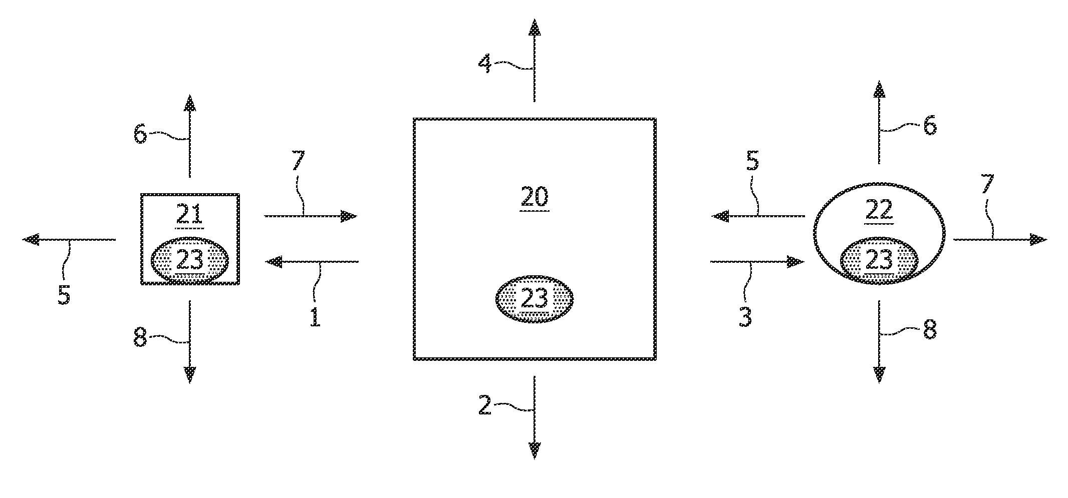
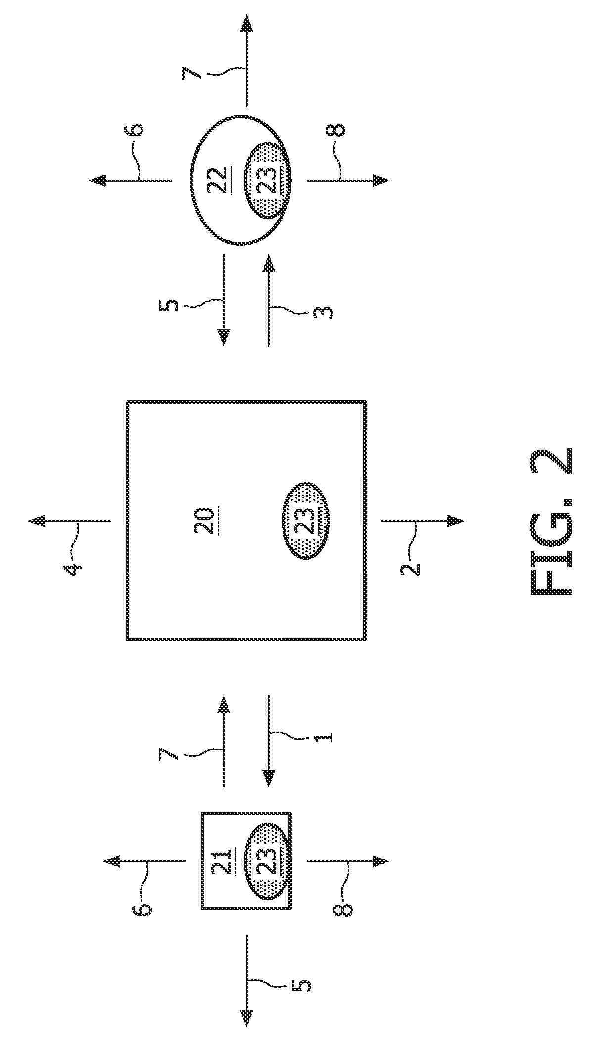
[0037]FIG. 2 illustrates the central light-emitting unit 20 and the peripherals 21, 22 according to the present invention. The central light-emitting unit comprises embedded identifiers in light 1, 2, 3, 4 as well as means for receiving embedded identifiers in light 23. The peripherals are also capable of transmitting identifiers 5, 6, 7, 8 and they comprise means for receiving identifiers or spatial configuration information embedded in light 23. Consequently, each device may simultaneously function as both a light-sensing device and a light-emitting device. Hence, each particular device may determine its relative location with respect to another device and as such create a full positional map of all devices which are connected together via a wired or wireless network.

third embodiment

[0038]FIG. 3 illustrates the present invention. FIG. 3 shows a room where the central light-emitting unit is a 3D display screen 30, one light-sensing device contained in a pair of headphones 31 and another light-sensing device contained in a remote control 32. When the headphones are moved relatively to the screen 33a, 33b, different identifiers 1, 2, 3 or 4 will be received along with different audio data. As a result, a 3D sound experience will be created next to the 3D visual experience of the screen. The remote control can in this embodiment also act as a triggering device handled by a user for controlling transmission of identifiers / configuration data of the central light-emitting device.


PUM


Abstract

The present invention relates to light-based communication, and more particularly it relates to methods for configuration of at least one remote light-sensing device, to a central light-emitting unit and to a light-sensing device. According to the invention, spatial configuration of remote light-sensing devices (e.g. peripherals such as loudspeakers or light devices), will be achieved by transmission of embedded identifiers or configuration information in light emitted in a plurality of directions from a central light-emitting unit. With a different identifier or different configuration information for each direction of transmission, the directions can be distinguished from each other. The invention enables a user to place remote light-sensing devices in a desired spatial position and the central light-emitting unit will be able to determine location and spatial function, i.e. for example whether the peripheral is an audio device and / or a lighting device. As a result, the peripherals will be correctly configured without any user interaction required.

Description

FIELD OF THE INVENTION[0001]The present invention relates to light-based communication, and more particularly it relates to methods for configuration of at least one remote light-sensing device, to a central light-emitting unit and to a light-sensing device.BACKGROUND OF THE INVENTION[0002]There is an increasing interest in the creation of spatial atmosphere based on home entertainment and multimedia content. In order to create such an atmosphere, spatial distribution of peripheral equipment, including for example loudspeakers, lighting devices and possibly devices for vibration, air and scent effects, is required. There is often a multitude of peripherals involved in the atmosphere creation and ideally one would want to connect all these devices wirelessly and automatically, and make them function correctly without any active user configuration.[0003]Traditionally, the link between a multimedia device and its peripherals is a wired connection. The setup of such a connection is ofte...

Claims


Application Information

Patent Timeline
Patent Type & Authority Patents(United States)
IPC IPC(8): H04B10/00H04B10/118
CPCH05B37/0272H05B47/105H05B47/195Y02B20/40H05B47/11H05B47/19
Inventor SCHENK, TIM CORNEEL WILHELMUSFERI, LORENZOVAN DE SLUIS, BARTEL MARINUSRONDA, CORNELIS REINDER
Owner KONINK PHILIPS ELECTRONICS NV
Why Eureka
Try Eureka