Energy efficient high intensity lighting fixture and method and system for efficient, effective, and energy saving high intensity lighting

a high intensity lighting and energy saving technology, applied in the field of lighting fixtures, can solve the problems of consuming a large amount of electrical energy for each sport lighting system, affecting the efficiency of lighting fixtures, so as to reduce operating costs, increase the amount of useable light, and effectively utilize the effect of light produced

Active Publication Date: 2014-07-08
MUSCO
View PDF58 Cites 11 Cited by
  • Summary
  • Abstract
  • Description
  • Claims
  • Application Information

AI Technical Summary

Benefits of technology

[0032]It is therefore a principal object, feature, or advantage of the present invention to present a high intensity lighting fixture, its method of use, and its incorporation into a lighting system, which improves over or solves certain problems and deficiencies in the art.

Problems solved by technology

Light energy has a cost.
Each sport lighting system consumes a significant amount of electrical energy to produce light from each fixture.
However, over 10 years, this can mean thousands of hours of operation.
However, taking a wider view, energy costs for thirty fixtures, for example, over 10 years, is significant.

Method used


Image

  • Energy efficient high intensity lighting fixture and method and system for efficient, effective, and energy saving high intensity lighting
  • Energy efficient high intensity lighting fixture and method and system for efficient, effective, and energy saving high intensity lighting
  • Energy efficient high intensity lighting fixture and method and system for efficient, effective, and energy saving high intensity lighting

Examples


Embodiment Construction

[0150]A. Overview

[0151]For a better understanding of the invention, exemplary embodiments will now be described in detail. Frequent reference will be made to the accompanying drawings. Reference numerals and letters will be used to indicate certain parts and locations in the drawings. The same reference numerals or letters will be used to indicate the same parts and locations throughout the drawings unless otherwise indicated.

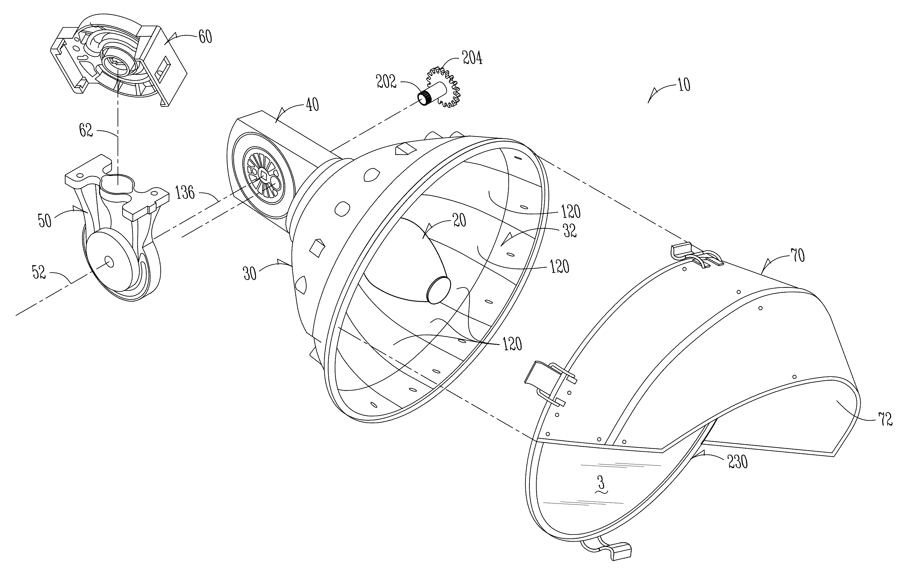
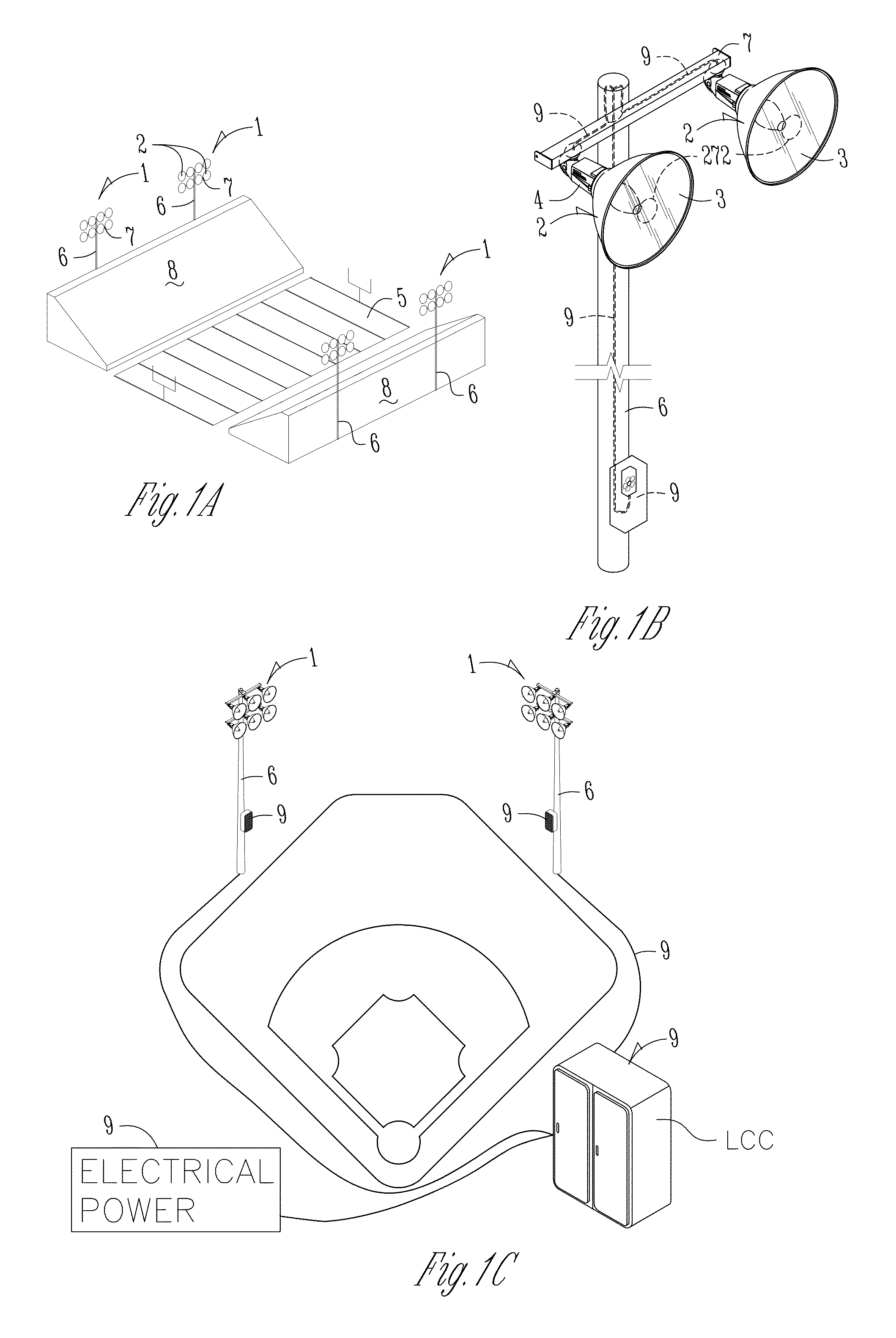
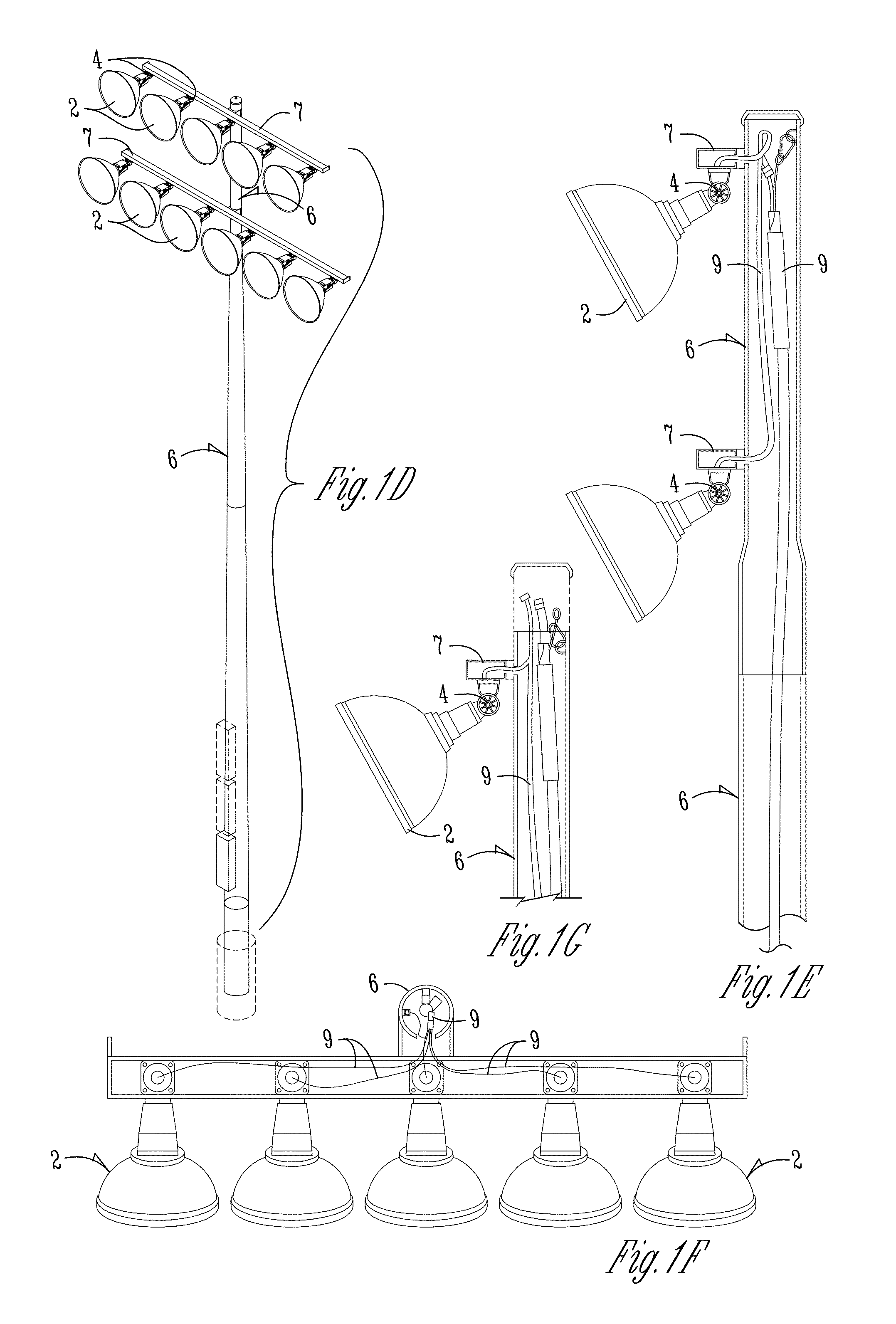
[0152]An embodiment of a light fixture will be described in the context of sports lighting, sports lighting fixtures, and sports lighting systems for the illumination of athletic fields such as shown in FIGS. 1A and 1C. The lighting must light the field and a volume of space above the field (collectively sometimes called the target area or target space), according to predetermined lighting level and uniformity specifications. The embodiment relates to fixtures that utilize high intensity discharge (HID) lamps, presently normally 1,000 watts or higher, of the me...


PUM


Abstract

A high intensity discharge (HID) light fixture includes a reflector frame which supports an independent high reflectivity reflecting surface. The reflector frame supports a glass lens with anti-reflective coatings on its surfaces and a visor or extension that also supports an independent high reflectivity reflecting surface. The high reflectivity reflecting surface has various sections that adjust portions of the beam created by the fixture to better place light on a target area. The reflector frame is attachable to a lamp cone. An adjustable knuckle attaches between to a cross arm on a pole and the lamp cone. An HID lamp, when mounted in the lamp cone, has its arc tube substantially surrounded by the high reflectivity reflecting surfaces of the reflector frame and visor. A lamp positioning mechanism automatically adjusts orientation of the arc lamp over a range of pivot angles for the lamp cone relative the knuckle. The HID lamp has an increased metal halide salt pool and does not include white oxide coatings at opposite ends. The lamp and the lamp positioning mechanism are configured to position the arc tube of the lamp horizontal over the normal range of aiming angles for the fixture. The modified HID lamp, its operating position, the high reflectivity reflecting surfaces, and other aspects of the fixture produce more light from the fixture than without these features for the same amount of energy to operate. Optionally, a ballast circuit can save energy over operating life of the lamp.

Description

CROSS REFERENCE TO RELATED APPLICATIONS[0001]This application claims priority under 35 U.S.C. §119 of a provisional application U.S. Ser. No. 60 / 644,784 filed Jan. 18, 2005, herein incorporated by reference in its entirety. This application is also a non-provisional of the following provisional U.S. applications, all filed Jan. 18, 2005: U.S. Ser. No. 60 / 644,639; U.S. Ser. No. 60 / 644,536; U.S. Ser. No. 60 / 644,747; U.S. Ser. No. 60 / 644,534; U.S. Ser. No. 60 / 644,720; U.S. Ser. No. 60 / 644,688; U.S. Ser. No. 60 / 644,636; U.S. Ser. No. 60 / 644,517; U.S. Ser. No. 60 / 644,609; U.S. Ser. No. 60 / 644,516; U.S. Ser. No. 60 / 644,546; U.S. Ser. No. 60 / 644,547; U.S. Ser. No. 60 / 644,638; U.S. Ser. No. 60 / 644,537; U.S. Ser. No. 60 / 644,637; U.S. Ser. No. 60 / 644,719; U.S. Ser. No. 60 / 644,687, each of which is herein incorporated by reference in its entirety.[0002]This application also claims priority to co-pending U.S. Ser. No. 10 / 785,867 filed Feb. 24, 2004.INCORPORATION BY REFERENCE[0003]The contents o...

Claims


Application Information

Patent Timeline
Patent Type & Authority Patents(United States)
IPC IPC(8): F21S8/00
CPCH05B41/392F21V23/026F21W2131/10F21W2131/105H05B41/40
Inventor GORDIN, MYRON K.BOYLE, TIMOTHY J.
Owner MUSCO
Why Eureka
Try Eureka