Set of dental drills

a dental drill and drill bit technology, applied in dental tools, dental surgery, medical science, etc., can solve the problems of excessive drilling depth, increased complexity and potential error, and drills too wide for a reduction sleeve or drill bit, so as to prevent excessive drilling depth

Active Publication Date: 2014-07-08
STRAUMANN HLDG AG
View PDF23 Cites 3 Cited by
  • Summary
  • Abstract
  • Description
  • Claims
  • Application Information

AI Technical Summary

Benefits of technology

[0009]Because the guide regions of the dental drills are of identical diameter, it is not necessary to change the reduction sleeve or the drilling spoon during the drilling process. The diameter of the guide region of the individual dental drills, and therefore the necessary inner diameter of the drill guide, is thus non-dependent on the diameter of the cutting portion of the dental drills. Since it is no longer necessary for the reduction sleeves to be changed during drilling, the drilling process is simplified.
[0010]In one embodiment, the guide regions of all dental drills of the set of dental drills are, additionally, of the same height. The height of the guide region has a determinant effect upon the maximum drilling depth that can be achieved with the corresponding dental drill. For this reason, it is advantageous if all dental drills of a set have a guide region of identical height, such that there is no risk of confusion in this regard.
[0013]In one embodiment, the shank portion of the dental drill additionally has an insertion region, for the lateral insertion of the dental drill into a drill guide. This insertion region is preferably designed to be narrower than the guide region. Depending on the width of the cutting portion of the dental drill, the insertion region is moreover preferably even narrower than the cutting portion of the dental drill. To enable the dental drills to be inserted laterally into a drill guide, this drill guide must have a lateral slot that is at least as broad as the insertion region of each dental drill. The provision of an insertion region on the dental drill makes it possible for even those drills having a particularly thick cutting portion, and particularly profile drills, to be inserted into a drill guide. As a result, optimum compliance with the required implantation axis can be ensured, even in the case of dental drills whose cutting portion is of a greater diameter than the inner diameter of the drill guide.
[0019]In one embodiment, the dental implantology set additionally has a drilling stop. The combination of the set of dental drills with a drill guide and a drilling stop enables the preparation of the implant bed to be realized in an optimal manner. The drill guide allows control of the optimum implantation axis, while the drilling stop prevents excessively deep penetration into the jaw bone.

Problems solved by technology

Because the reduction sleeves or drilling spoons must be exchanged continually, this results in increased complexity and potential for error.
Moreover, in the case of individual dental drills, particularly in the case of profile drills, it can be the case that these drills are too broad for a reduction sleeve or drilling spoon.
In this case, the drilling has to be performed without guidance, and the risk of a drilling inaccuracy is significantly greater.

Method used


Image

  • Set of dental drills
  • Set of dental drills
  • Set of dental drills

Examples


Embodiment Construction

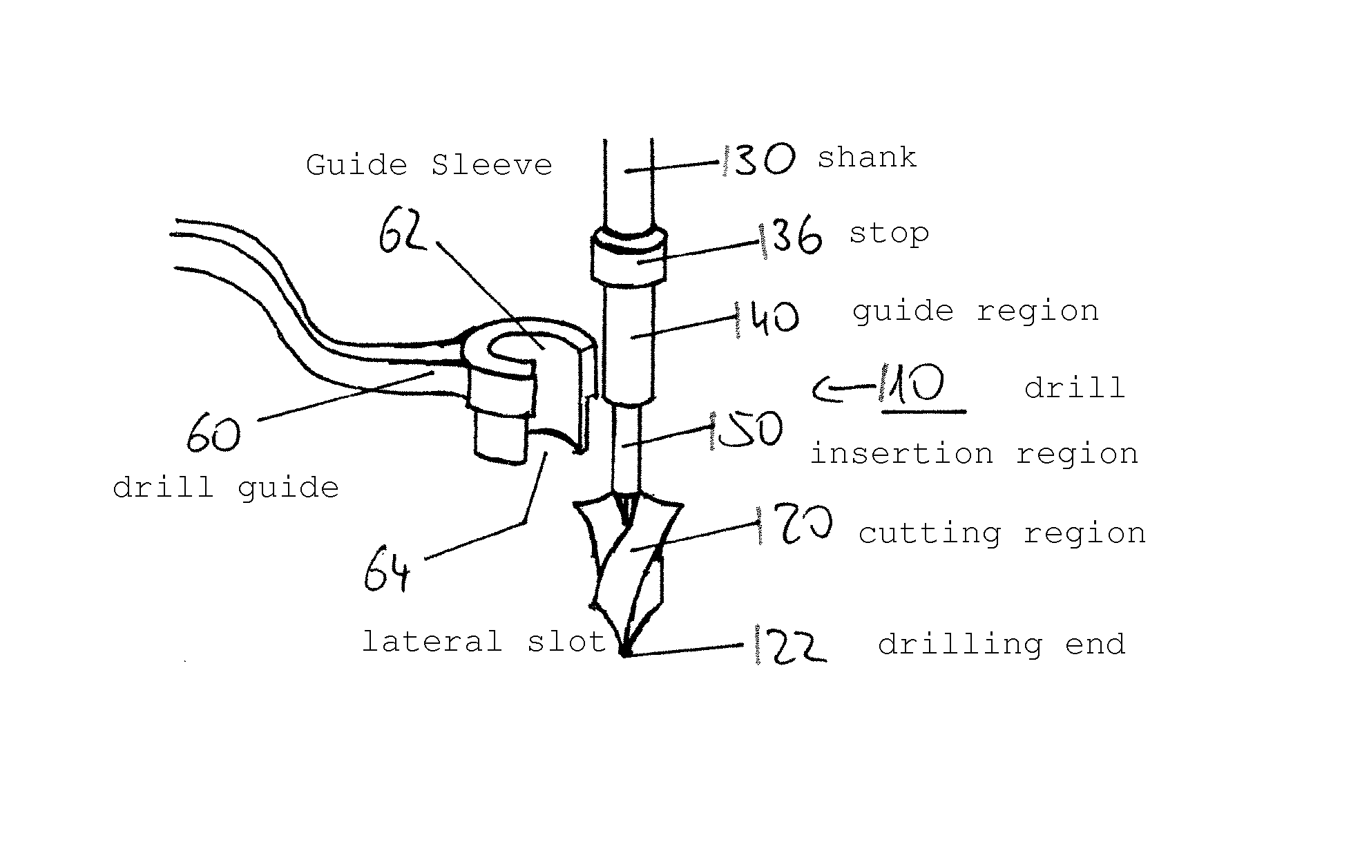
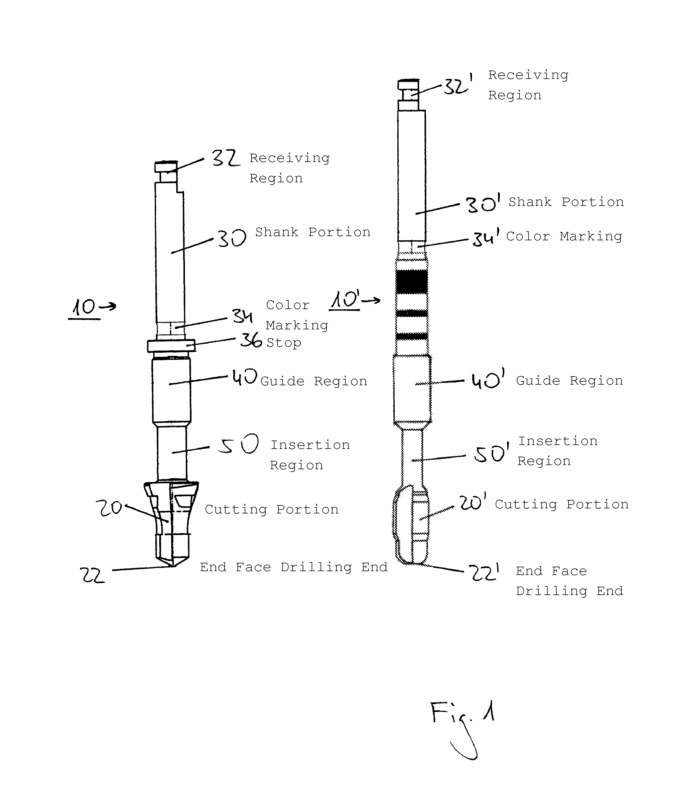
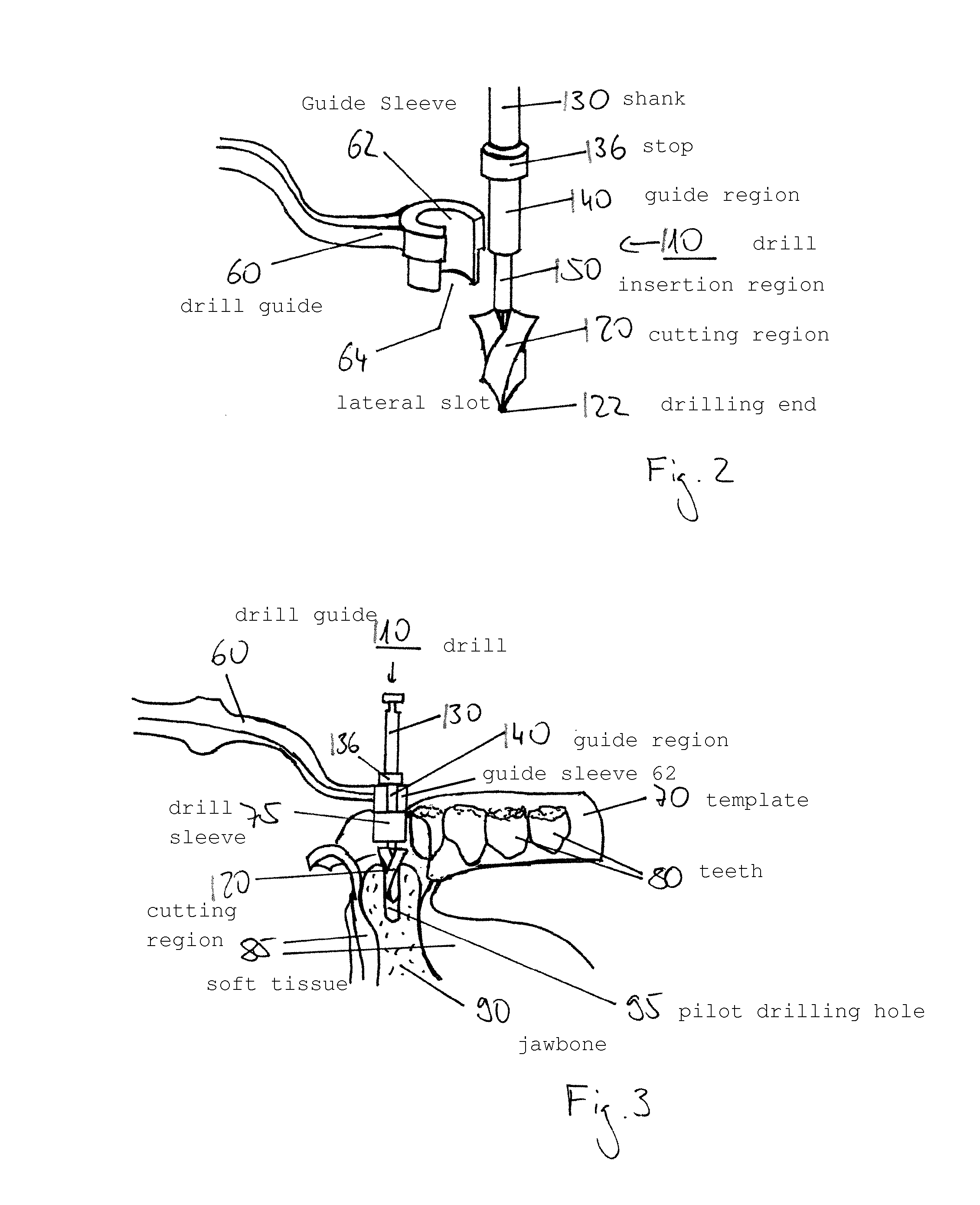
[0024]FIG. 1 shows a set of two dental drills 10, 10′, consisting of a profile drill 10 and a threading tap drill 10′. Each of the dental drills 10, 10′ has a cutting portion 20, 20′ and a shank portion 30, 30′. An end-face drilling end 22, 22′ is provided at the lower end of the cutting portion 20, 20′. At the upper end of the shank portion 30, 30′ there is a receiving region 32, 32′, which is intended to be received in a drill holding device. The shank portions 30, 30′ moreover have a substantially circular-cylindrical guide region 40, 40′ for guiding the dental drill 10, 10′ during the drilling process. The guide regions 40, 40′ of the two dental drills 10, 10′ are of the same diameter. The shank portions 30, 30′ additionally have an insertion region 50, 50′, which enables the dental drills to be inserted laterally into a drill guide. The diameter of the respective cutting portion 20, 20′ is coded by a color marking 34, 34′ on the shank portions 30, 30′ of the dental drills 10, 1...


PUM


Abstract

Set of dental drills having two or more dental drills (10, 10′), each of dental drills (10, 10′) having a cutting portion (20, 20′) that has an end-face drilling end (22, 22′) and a shank portion (30, 30′) that has a receiving region (32, 32′) intended to be received in a drill holding device. The shank portions (30, 30′) of the dental drills each have a substantially circular-cylindrical guide region (40, 40′) for guiding the dental drills, the guide regions (40, 40′) of the two or more dental drills being of the same diameter.

Description

FIELD OF THE INVENTION[0001]The present invention relates to a set of dental drills.BACKGROUND[0002]Known in dental implantology, for the preparation of an implant bed, is the practice of using a set of a plurality of differing dental drills, which set comprises, for example, a milling cutter, a pilot drill, a profile drill, a spiral drill (also twist drill) and a threading tap drill.[0003]Broadly, the procedure in the preparation of an implant bed is as follows: Firstly, the bone surface is exposed, and smoothed by means of a milling cutter. The implantation site is marked by means of the milling cutter, and possibly widened, in which latter case a plurality of milling cutters of increasing diameters are used. The implant bed is then prepared by means of appropriate pilot drills, in order to determine the drilling axis. The drilled hole is widened to the required size by means of spiral drills. A profile drill is used to match the profile of the drilled hole to the shape of the pro...

Claims


Application Information

Patent Timeline
Patent Type & Authority Patents(United States)
IPC IPC(8): A61C3/02A61C8/00
CPCA61C8/0089A61C3/02
Inventor SUTER, EDMUNDKUHNE, STEFFENSTREFF, PATRICK
Owner STRAUMANN HLDG AG
Why Eureka
Try Eureka