
Image forming method

a technology of image and forming method, applied in the field of image forming method, can solve the problems of inability to rotate, slippage of images, microscopic wrinkles, etc., and achieve the effect of enhancing gloss and inhibiting the occurrence of slippage of images

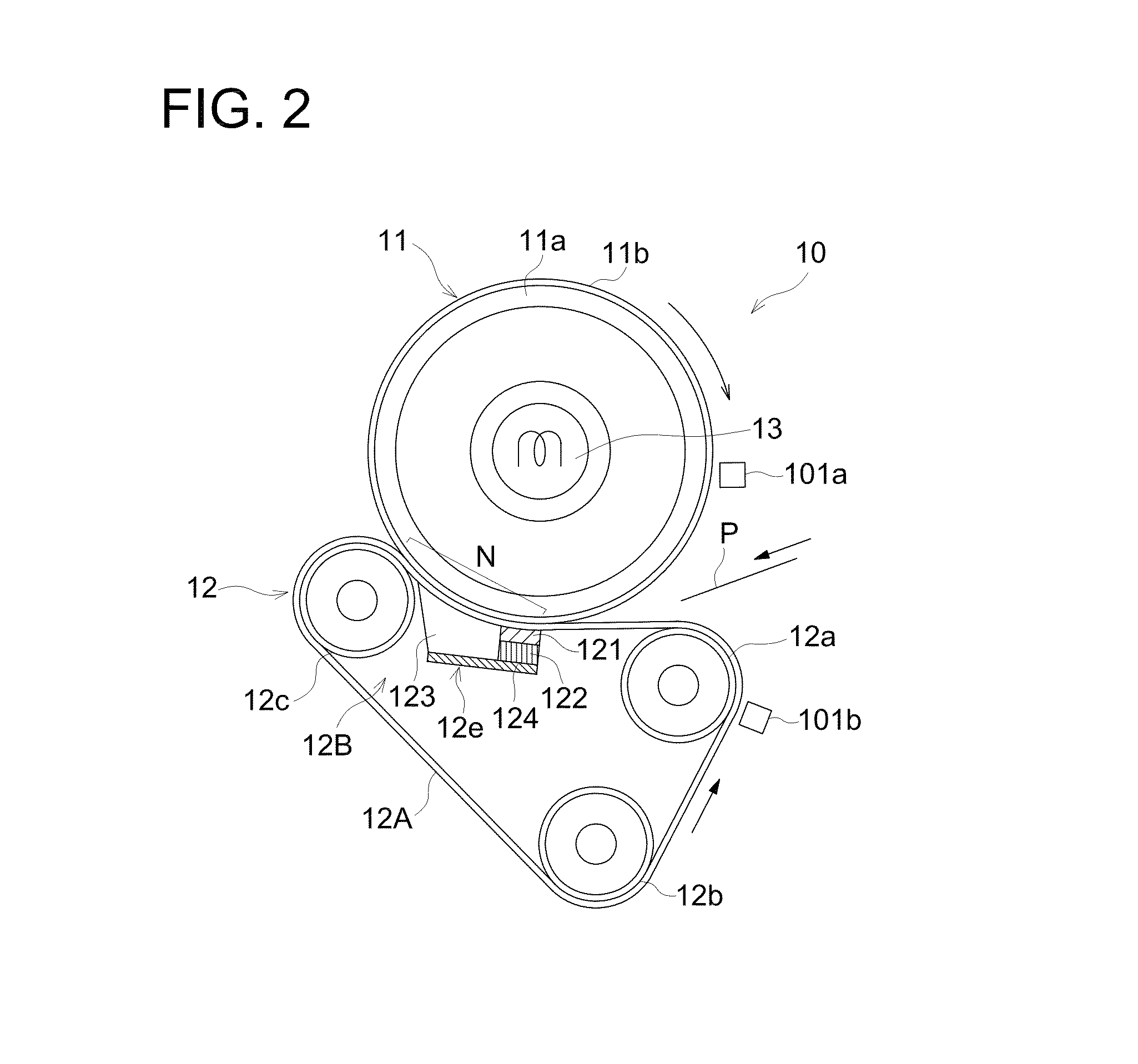
Inactive Publication Date: 2014-07-08
KONICA MINOLTA BUSINESS TECH INC
View PDF13 Cites 0 Cited by
  • Summary
  • Abstract
  • Description
  • Claims
  • Application Information

AI Technical Summary

Benefits of technology

[0007]The present invention has come into being taking into account the foregoing circumstances. It is an object of the present invention to provide a method for forming images with enhanced gloss with inhibiting occurrence of slippage of images.
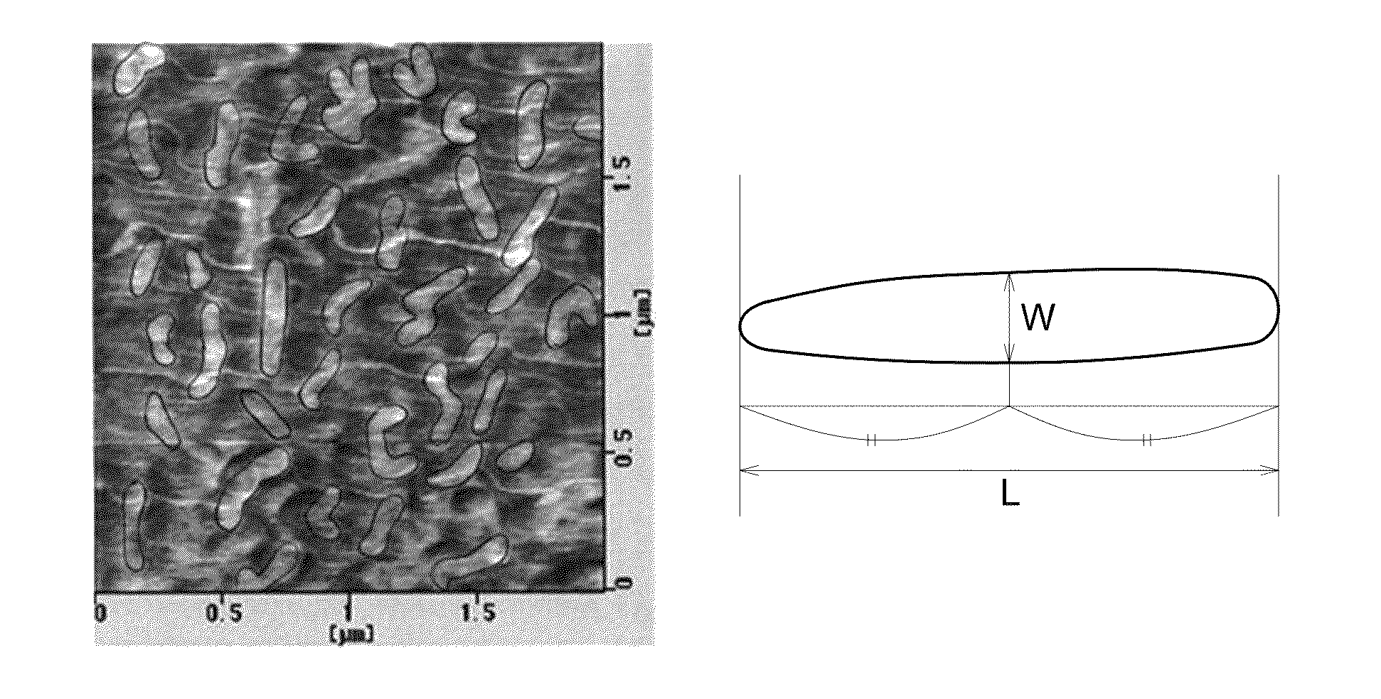
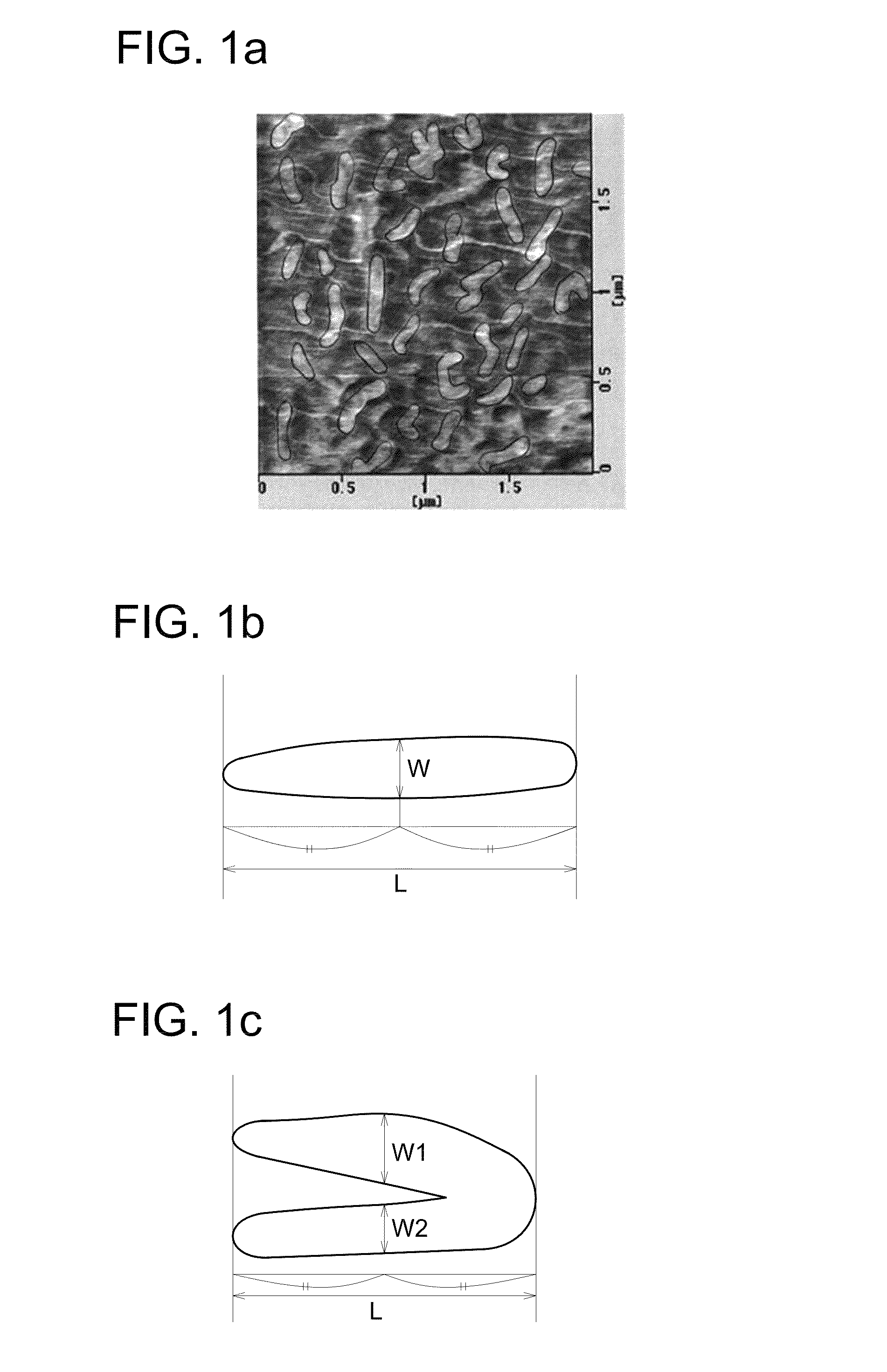
[0013]To make it feasible to achieve enhanced glossiness and inhibit slippage of images, there was studied functional separation of the respective effects, and a toner was prepared which was composed of a resin of low softening point and low elasticity in terms of high glossiness and a resin of high elasticity in terms of prevention of slippage of images. However, it was proved that sufficient effects were not achieved by control of the structure of toner particles employing the conventional technology. So, a toner was prepared through an orientation manner of a resin having a domain matrix structure and enhanced glossiness was achieved by reducing the size of the spherical domain to a level of less than the visible light wavelength but prevention of slippage of images was still not satisfactory.
[0014]Accordingly, the problems of the present invention were overcome by use of a toner comprised of a binder resin having introduced a domain of being sort of the rod shape, that is, the shape as defined in the present invention (hereinafter, also denoted as “specific shape”). According to the image forming method of the present invention, when using a fixing device of a belt-nip system, the use of a specific toner inhibited occurrence of slippage of images, while achieving glossiness of the formed image.
[0015]The reason that occurrence of slippage of images is inhibited with achieving glossiness of the formed image when using a fixing device of a belt-nip system can be presumed to be as follows. Generally, in a system of plural resins differing in thermal property being present as a mixture, the whole of the system exhibits an averaged thermal property. However, it is presumed that, in binder resins related to the present invention, a high-elastic resin constituting a domain (which is hereinafter also denoted as a domain resin) and a low-elastic resin forming a matrix (which is hereinafter also denoted as a matrix resin) are greatly different in thermal property, so that the matrix resin and the domain resin exhibit no interaction with each other at a lower end of the fixing temperature, and only the matrix resin exhibiting a low softening point melts and the domain resin is not involved in melting, so that the domain resin does not disturb melting deformation of a toner.
[0016]One of causes for occurrence of slippage of images is presumed to be that, in the stage of fixing, the elasticity of a melted toner within a fixing nip section is lowered and slide slippage is caused between the fixing member and the transfer member, and thereby, microscopic rupture is generated on the image surface, leaving wrinkles. It is also presumed that, in the image forming method of the present invention, the use of a toner in which the domain is a binder resin having a specific form enhances the grip power of a toner forming a toner image onto a transfer material, inhibiting occurrence of slippage of images.

Problems solved by technology

However, such a fixing device of a belt-nip system, in which a pressure-applying member with an upper surface formed of an elastic layer such as rubber is disposed with being brought into contact with the inner circumference of an endless belt, results in increased slide resistance, leading to unstable rotary movement and producing problems such as occurrence of slippage of images.
Specifically in cases when forming a solid image with an increased toner adhesion amount, occurrence of slippage of images results in microscopic wrinkles, which are visibly observed as uneven gloss.
However, such techniques complicate the constitution of a fixing device, producing problems such that an exchange cycle is shortened along with deterioration of the belts or slide sheets.

Method used


Image

  • Image forming method
  • Image forming method
  • Image forming method

Examples


example 1

Step (a-1): Preparation of Resin Particle Dispersion

(1) First Polymerization:

[0178]Into a 5 liter reaction vessel fitted with a stirrer, a temperature sensor, a condenser and a nitrogen introducing device was placed a surfactant solution and the liquid temperature was raised to 80° C., while stirring at a rate of 230 rpm under a nitrogen gas stream. The surfactant solution contained 2 parts by mass of an anionic surfactant (sodium dodecylbenzenesulfonate, which is hereinafter also denoted as SDS) and 2900 parts by mass of deionized water. To the surfactant solution was added 9 parts by mass of a polymerization initiator (potassium persulfate, which is hereinafter also denoted as KPS). Further thereto, a monomer solution comprised of 550 parts by mass of styrene, 280 parts by mass of n-butyl acrylate, 45 parts by mass of methacrylic acid and 14.5 parts by mass of n-octyl mercaptan was dropwise added over 3 hours and after completing the addition, the reaction mixture was maintained a...

example 2

[0194]A toner (2) comprised of toner particles (2) was prepared in the same manner as in Example 1, except that the dispersion (B1) of resin particles (B1) used in the step (d) was replaced by a dispersion (B2) of resin particles (B2), and the amounts of the dispersion (A1), the dispersion (B2) and deionized water were changed to 298 parts by mass (solids), 138 parts by mass (solids) and 1695 parts by mass, respectively.

Step (b): Preparation of Resin Particle Dispersion (B2)

[0195]Into a 5 liter reaction vessel fitted with a stirrer, a temperature sensor, a condenser, and a nitrogen introducing device was placed a surfactant solution and the liquid temperature was raised to 80° C. with stirring at a rate of 230 rpm under a nitrogen gas stream. The surfactant solution composed of 1.5 parts by mass of an anionic surfactant, sodium dodecylsulfate (SDS) and 1550 parts by mass of deionized water. To the surfactant solution was added 15 parts by mass of a polymerization initiator, sodium p...

example 3

[0196]A toner (3) comprised of toner particles (3) was prepared in the same manner as in Example 1, except that the dispersion (B1) of resin particles (B1) used in the step (d) was replaced by a dispersion (B3) of resin particles (B3), and the amounts of the dispersion (A1), the dispersion (B3) and deionized water were changed to 413 parts by mass (solids), 23 parts by mass (solids) and 1695 parts by mass, respectively.

Step (b): Preparation of Dispersion (B3) of Resin Particles (B3)

[0197]Into a 5 liter reaction vessel fitted with a stirrer, a temperature sensor, a condenser and a nitrogen introducing device was placed a surfactant solution and the liquid temperature was raised to 80° C. with stirring at a rate of 230 rpm under a nitrogen gas stream. The surfactant solution was composed of 3.6 parts by mass of an anionic surfactant (SDS) and 1550 parts by mass of deionized water. To the surfactant solution was added 15 parts by mass of a polymerization initiator (KPS). Further theret...


PUM


Abstract

An image forming method is disclosed, comprising transferring and fixing steps, wherein fixing is performed by a fixing device in which at least one of a heating member and a pressing member comprises an endless belt entrained about plural rollers, and the heating member and the pressing member are pressed against each other to form a fixing nip, and wherein toner particles contains a binder resin which has a domain / matrix structure constituted of a high-elastic resin forming a domain and a low-elastic resin forming a matrix in an elastic image obtained when observing the toner particles by an atomic force microscope with respect to a section of the individual toner particles, in which an arithmetic average value of a ratio (L / W) of a major axis (L) to a minor axis (W) of individual domains is 1.5 to 5.0, and domains having the major axis (L) of 60 to 500 nm account for not less than 80% by number of total domains and domains having the minor axis (W) of 45 to 100 nm account for not less than 80% by number of total domains.

Description

[0001]This application claims priority from Japanese Patent Application No. 2010-094725, filed on Apr. 16, 2010, which is incorporated hereinto by reference.FIELD OF THE INVENTION[0002]The present invention relates to an image forming method by use of an electrophotographic toner.BACKGROUND OF THE INVENTION[0003]There have been proposed fixing devices of various systems to heat-fixing unfixed toner images in an image forming apparatus such as an electrophotographic copying machine, printer, or facsimile. Such fixing devices include, for example, a fixing device of a belt-nip system in which a fixing belt is pressed against a heating member or a pressing member.[0004]There is cited, for example, a fixing device of a belt-nip system, as disclosed in JP 2004-109878A, which is constituted of a rotatably supported heating member, an endless belt with its outer circumference pressed against the heating member, the inner circumference of the endless belt and a pressure-applying member, pre...

Claims


Application Information

Patent Timeline
Patent Type & Authority Patents(United States)
IPC IPC(8): G03G13/20
CPCG03G15/2064G03G9/0819G03G9/08795G03G9/08797G03G2215/2009
Inventor UEDA, NOBORUNAGASAWA, HIROSHIHORI, ANJU
Owner KONICA MINOLTA BUSINESS TECH INC
Learn More