Medical viewing system for displaying a region of interest on medical images

a medical imaging and viewing system technology, applied in image enhancement, angiography, instruments, etc., can solve the problems of not being able to solve or to a multitude of solutions, difficult to make the clinician aware, and difficult to assess how much the considered object should be in the image, so as to reduce the accuracy of object-based registration and less distraction

Active Publication Date: 2014-07-08
KONINK PHILIPS ELECTRONICS NV
View PDF9 Cites 20 Cited by
  • Summary
  • Abstract
  • Description
  • Claims
  • Application Information

AI Technical Summary

Benefits of technology

[0007]Accordingly, there may be a need for a medical viewing system which may allow to overcome at least some of the above insufficiencies. Particularly, there may be a need for a medical viewing system that provides an accurate road mapping in ensuring the sufficient visibility of reference objects for detection of real cardiac phases of live fluoroscopy images.
[0013]A gist of the present invention is to display the limit of a region in which the considered targeted object must be partially present to ensure an optimal processing of the road mapping procedure. A clinician positioning the targeted object within this region will have brought it far enough in the image. The medical viewing system according to the present invention reminds the clinician of the importance of pushing the object far enough into the image, while being discrete enough to be ignored if preferred. The clinician expecting a reliable road mapping must provide enough information to allow its computation. By displaying a region of interest over the image the invention invites him to push e.g. a catheter injection tip far enough into the image to constrain the superimposition problem enough. This leads to a more reliable and precise road mapping processing.
[0017]The size of the region of interest border generated by the calculating unit is adaptable to anatomical priors in a further embodiment of the present invention. This enables the medical viewing system according to the present invention to adapt to different tasks and different interventional areas of the patient. During percutaneous coronary intervention a larger region of interest border may be needed than in other interventional procedures where the related organs do not move as heavily as in the heart region.
[0018]In a further exemplary embodiment of the present invention the system provides the ability for an exam phase determination in order to adapt the region of interest border overlay on the display unit and to remove the overlaid border respectively. For example, during fluoroscopy live image acquisition all advantages of the present invention can be taken. On the other hand, during acquisition of the angiograms it is not necessary and may also be distracting to see the region of interest border.
[0019]According to a still further embodiment of the present invention the overlay of the border of the region of interest on the display unit can be switched off manually, leading to less distraction of the clinician if it is considered clear—preferably by the medical viewing system according to the present invention—that the considered targeted object for the object-based registration is situated inside the related region of interest.

Problems solved by technology

However, if the expected object, e.g. the catheter tip, is only partially visible in the acquired live images, the results of a related object-based registration algorithm is ill-posed and may lead to no solution or to a multitude of solutions, among which every one but one are erroneous.
It is difficult to make the clinician aware of the importance of the visibility of key objects for the success of the road mapping procedure.
Further, it is difficult to assess how much the considered object should be in the image when one is not familiar with the details of the related road mapping processing.
Even if one specifies precisely the conditions to be fulfilled for the processing success and the required accuracy, e.g. a certain visible length of the object in millimeters, or a certain number of pixels, at intervention time, fulfilling those precise specifications is a burden for the clinician.

Method used


Image

  • Medical viewing system for displaying a region of interest on medical images
  • Medical viewing system for displaying a region of interest on medical images
  • Medical viewing system for displaying a region of interest on medical images

Examples


Embodiment Construction

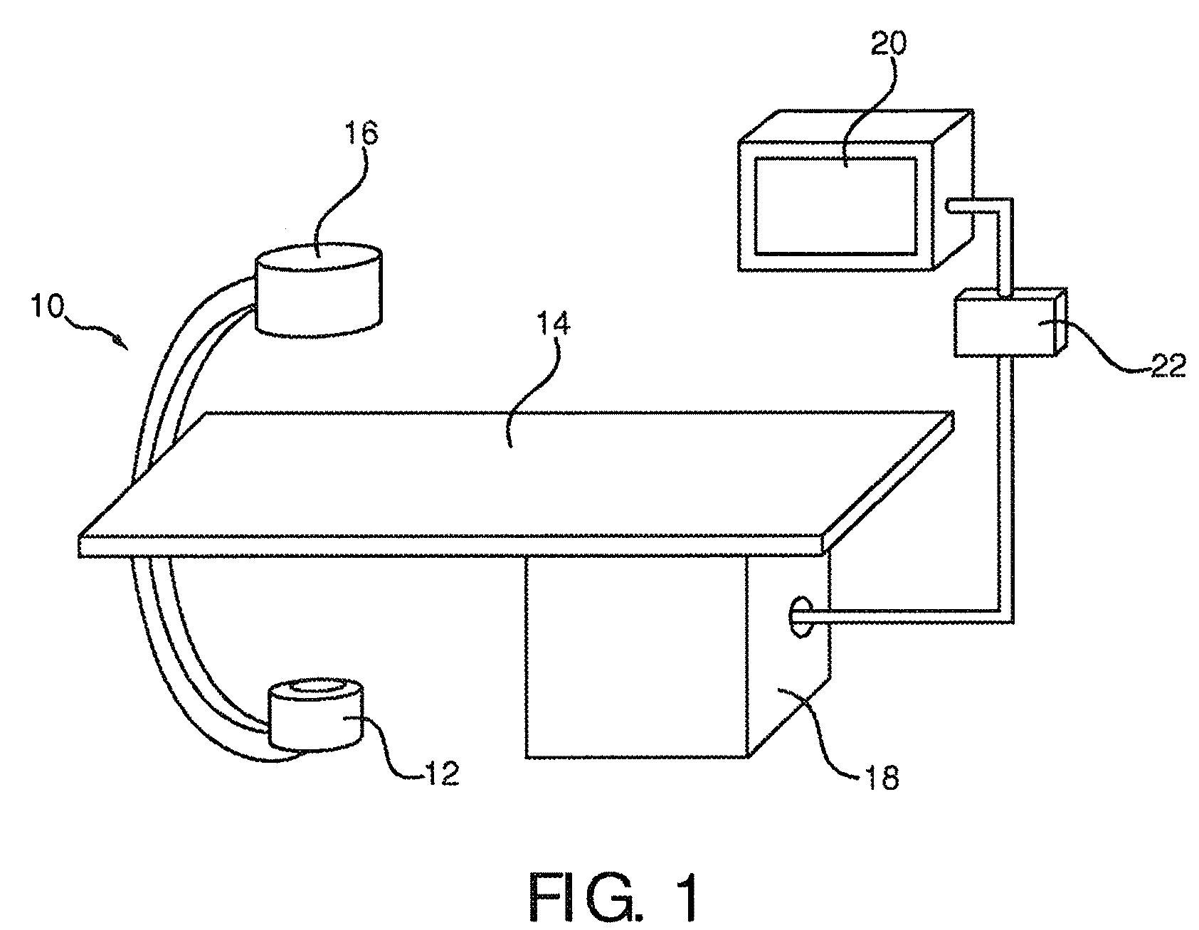
[0034]FIG. 1 schematically shows an X-ray imaging system 10 with a medical viewing system for generating a region of interest border and overlaying the border on vessel tree images and live images.

[0035]The X-ray imaging system 10 comprises an X-ray image acquisition device with a source of X-ray radiation 12 provided to generate X-ray radiation. A table 14 is provided to receive a subject to be examined. Further an X-ray image detection module 16 is located opposite the source of X-ray radiation 12. During the radiation procedure the examined subject is located between the source of X-ray radiation 12 and the detection module 16. The latter sends data to a data processing unit or calculation unit 18, which is connected to both the X-ray image detection module 16 and the X-ray radiation source 12. The calculation unit 18 is exemplarily located underneath the table 14 for saving space within the examination room. Of course, it could also be located at a different place, such as in a ...


PUM


Abstract

A medical viewing system with an X-ray image acquisition device for acquiring angiograms and interventional live images of vessels is adapted for generating a region of interest border into which an object referenced by an object-based registration process must extend in order to achieve an accurate registration of vessel trees extracted from the angiogram and the live images. The region of interest border is then overlaid onto the vessel tree images and the live images. The medical viewing system reminds the person accomplishing the intervention of the importance of pushing the object far enough into the image, while being discrete enough to be ignored if preferred, thus yielding in a reliable and precise road mapping processing.

Description

FIELD OF THE INVENTION[0001]The present invention is related to a medical viewing system and a method for displaying a region of interest on medical images representing positioning devices in a blood vessel.BACKGROUND OF THE INVENTION[0002]For the purpose of interventions, for example as applied in catheter labs under fluoroscopy when treating coronary stenoses, it is known to visualize vessel structures and devices advanced inside the vessel structures. Hereby, firstly a contrast agent is injected via a catheter and an X-ray examination apparatus records an angiographic sequence, which is also called an “angiogram”, that shows the vessels that are radio-opaque when filled with the contrast agent. Secondly, during the intervention, for example a flexible, partially or fully radio-opaque guide wire is advanced to affected vascular structures and by means of low-dose fluoroscopic X-ray surveillance the guide wire is visualized, which is referred to as “live images”. By means of an ove...

Claims


Application Information

Patent Timeline
Patent Type & Authority Patents(United States)
IPC IPC(8): H05G1/64
CPCA61B6/504A61B6/469A61B6/481G06T7/0028G06T2207/10116G06T2207/30101G06T7/33
Inventor VAN DEN HOUTEN, PETERBAKKER, NICOLAAS HYLKEFLORENT, RAOULAUVRAY, VINCENT MAURICE ANDRE
Owner KONINK PHILIPS ELECTRONICS NV
Why Eureka
Try Eureka