Cooling system of ring segment and gas turbine

a cooling system and gas turbine technology, applied in the direction of machines/engines, mechanical equipment, liquid fuel engines, etc., can solve the problems of loss of cooling air, high temperature combustion, and damage to so as to reduce the amount of cooling air of the gas turbine, enhance the cooling of the upstream end portion of the ring segment, and improve the thermal efficiency of the gas turbine

Active Publication Date: 2014-07-15
MITSUBISHI HEAVY IND LTD
View PDF7 Cites 13 Cited by
  • Summary
  • Abstract
  • Description
  • Claims
  • Application Information

AI Technical Summary

Benefits of technology

[0016]The present invention provides the first cavity in the upstream end portion of the ring segment in the flow direction of the combustion gas, and since the cooling air of the cooling space is supplied to the first cavity via the first cooling passage, and furthermore discharged to the combustion gas space from the downstream end portion in the flow direction of the combustion gas via the second cooling passage, the length of the cooling passage is elongated, and the convection cooling of the upstream end portion of the segment body which has an intense heat load is enhanced. For that reason, thermal damage of the upstream end portion of the segment body by the high temperature combustion gas is avoided.
[0037]According the aforementioned present invention, the cooling of the upstream end portion of the ring segment is enhanced, and thermal damage of the ring segment is avoided. Also, it is possible to provide a gas turbine that keeps down the amount used of cooling air to a minimum, and further increases the cooling efficiency and cooling performance of a ring segment. Accordingly, it is possible to improve the reliability and the operating efficiency of a gas turbine.

Problems solved by technology

However, in the invention disclosed in Patent Document 1, there is a region in which a cooling passage is not disposed on the upstream end portion of the ring segment in the flow direction of the combustion gas, and so in the case of the combustion gas further increasing in temperature, the problem arises of the upstream end portion of the ring segment being damaged thermally by the high temperature combustion gas.
However, since the cooling air that is discharged to the upstream end side of the ring segment in the flow direction of the combustion gas is discharged to the combustion gas space cooling only the upstream end portion, the problem arises of it becoming a loss of the amount of cooling air, and an increase in the amount of cooling air leads to a reduction in the thermal efficiency of the gas turbine.

Method used


Image

  • Cooling system of ring segment and gas turbine
  • Cooling system of ring segment and gas turbine
  • Cooling system of ring segment and gas turbine

Examples


first embodiment

[0051]A description of the first embodiment shall be given based on FIGS. 1 to 7 and FIG. 11.

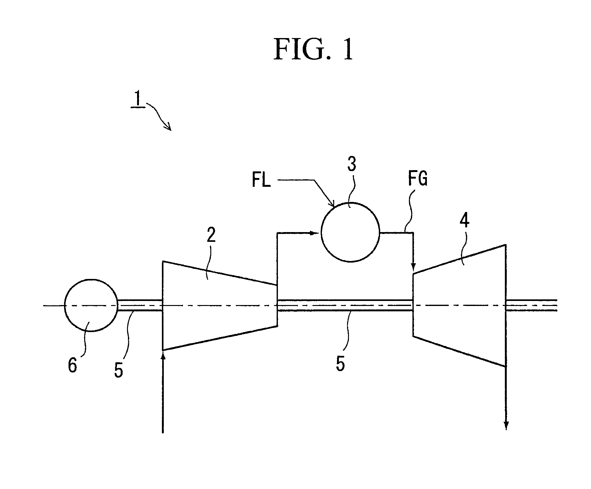
[0052]FIG. 1 is an overall configuration diagram of the gas turbine. A gas turbine 1 has as main constituent elements a compressor 2 that compresses combustion air, a combustor 3 that injects fuel FL into the combustion air that is sent from the compressor 2, causes a combustion, and generates combustion gas, a turbine 4 that is positioned on the downstream of this combustor 3 and driven by the combustion gas that has left the combustor 3, a generator 6, and a rotating shaft 5 that integrally couples the compressor 2, the turbine 4, and the generator 6.

[0053]Since the turbine 4 has the same constitution as the content described in FIG. 11 of the background art, a detailed description thereof shall be omitted. The same names and reference numerals shall be used for common component names and reference numerals.

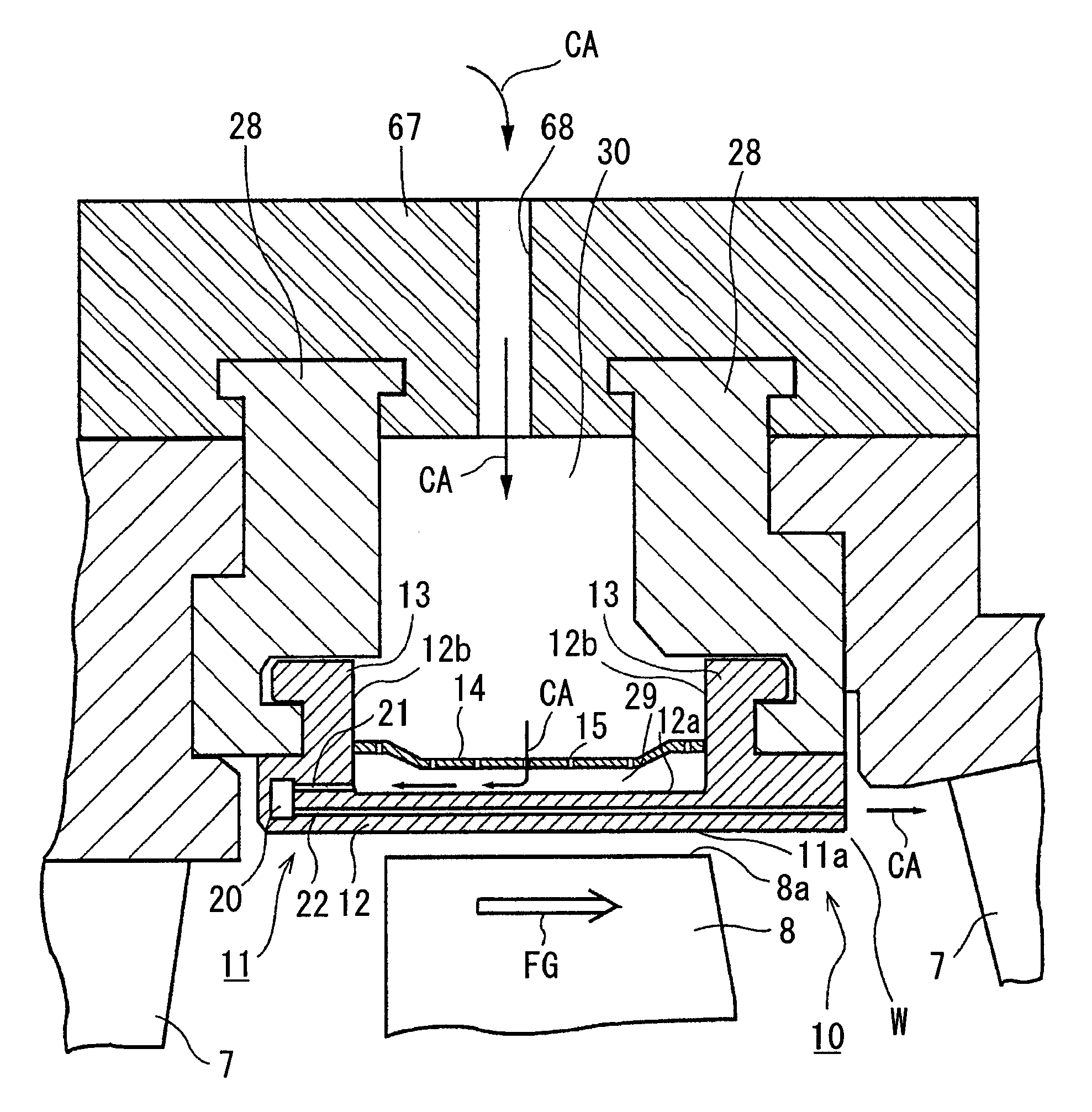
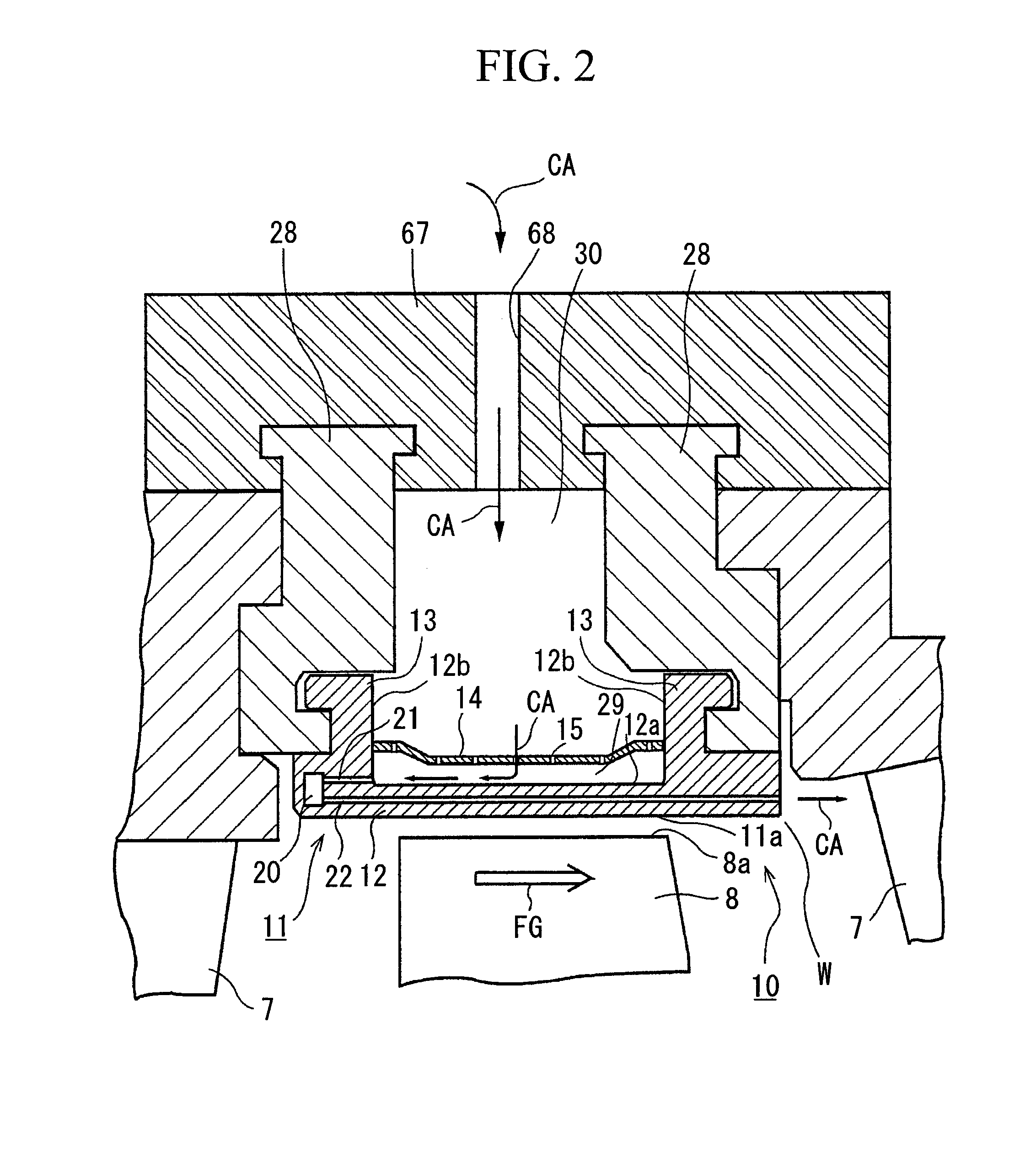
[0054]FIG. 2 shows a cross section of the essential portions of the ring segment of...

first modification

[0081]FIG. 8 shows an arrangement example that differs from the first embodiment, in relation to the first cooling passage and the second cooling passage. The first modification, compared to the first embodiment, is the same on the point of arranging cooling passages in an annular shape at the same hole pitch with respect to the rotation direction R of the rotating shaft 5, but differs on the point of the second cooling passage 22 having a smaller hole diameter than the first cooling passage 21. Also, it differs on the point of the hole pitch of the second cooling passage 22 in the rotation direction R of the rotating shaft 5 being greater than the hole pitch of the second cooling passage 22 in the rotation direction R. If these hole diameters and hole pitches of the first cooling passage 21 and the second cooling passage 22 are adopted, a sufficient amount of the cooling air that is supplied to the second cooling passage is secured for cooling, and compared to the first embodiment,...

second embodiment

[0083]FIG. 9 shows a partial cross-section of the upstream end portion of the segment body of the second embodiment.

[0084]Compared to the first embodiment, the present embodiment differs on the point of the first cooling passage having a slope in the axial direction of the rotating shaft with respect to the second cooling passage, and in other aspects is the same as the first embodiment. Note that the component elements that are in common with the first embodiment use the same component names and reference numbers as the first embodiment, and detailed descriptions thereof shall be omitted.

[0085]In FIG. 9, it is the same as the first embodiment on the point of a second cooling passage 45 being arranged in the axial direction of the rotating shaft 5 along the inner circumferential surface 11a of the segment body 11 until the downstream end face 17a, and being arranged in an annular shape at the same hole pitch in the rotation direction R of the rotating shaft. However, it differs on t...


PUM


Abstract

A cooling system of ring segment is provided with: a collision plate that has a plurality of small holes; a cooling space that is enclosed by the collision plate and a main body of the segment body; a first cavity that arranged is the upstream end portion of the segment body in the flow direction of the combustion gas so as to be perpendicular to the axial direction of a rotating shaft; a first cooling passage that communicates from the cooling space to the first cavity; and a second cooling passage that communicates from the first cavity to a fire combustion gas d gas space in the downstream end portion of the segment body in the flow direction of the combustion gas.

Description

BACKGROUND OF THE INVENTION[0001]1. Field of the Invention[0002]The present invention relates to a cooling system of ring segment of a gas turbine and to a gas turbine.[0003]2. Description of the Related Art[0004]Conventionally, since combustion gas of a high temperature and high pressure passes through the turbine of a gas turbine, which is used in the generation of electrical energy, cooling of the ring segment and the like is important in order to continue stabilized operation. In particular, due to improvements in the thermal efficiency of gas turbines in recent years, the temperature of combustion gas continues to increase.[0005]FIG. 11 is a cross-sectional view that shows the internal structure relating to the turbine of a gas turbine. The gas turbine supplies combustion gas FG generated in a combustor 3 to turbine vanes 7 and turbine blades 8, and by causing the turbine blades 8 to rotate around a rotating shaft 5, converts rotational energy into electrical power. The turbine...

Claims


Application Information

Patent Timeline
Patent Type & Authority Patents(United States)
IPC IPC(8): F01D25/08
CPCF01D25/12F05D2260/201F01D11/08F05D2240/81F01D11/24F01D11/00F02C7/28
Inventor KOYABU, HIDEMICHIHADA, SATOSHI
Owner MITSUBISHI HEAVY IND LTD
Why Eureka
Try Eureka