
Bicycle control apparatus

a control apparatus and bicycle technology, applied in bicycle equipment, electric propulsion mounting, transportation and packaging, etc., can solve the problem of insufficient assistance force, and achieve the effect of improving riding comfort, and suppressing the decrease of assistance for

Active Publication Date: 2014-07-15
SHIMANO INC
View PDF17 Cites 19 Cited by
  • Summary
  • Abstract
  • Description
  • Claims
  • Application Information

AI Technical Summary

Benefits of technology

The present invention improves the riding comfort of a bicycle that is assisted with a drive assistance electric motor. The control apparatus detects the pedaling force and increases the ratio of the output of the electric motor with respect to the pedaling force after a downshift that will cause the assistance force to decrease, resulting in a more stable and comfortable ride. Additionally, the ratio of the electric motor output remains increased until a prescribed condition is detected, preventing a decrease in output. Overall, the control apparatus improves the efficiency and comfort of the bicycle's assisted ride.

Problems solved by technology

Consequently, the assistance force feels insufficient when climbing, which is when assistance from the drive assistance electric motor is particularly desired.

Method used


Image

  • Bicycle control apparatus
  • Bicycle control apparatus
  • Bicycle control apparatus

Examples


first embodiment

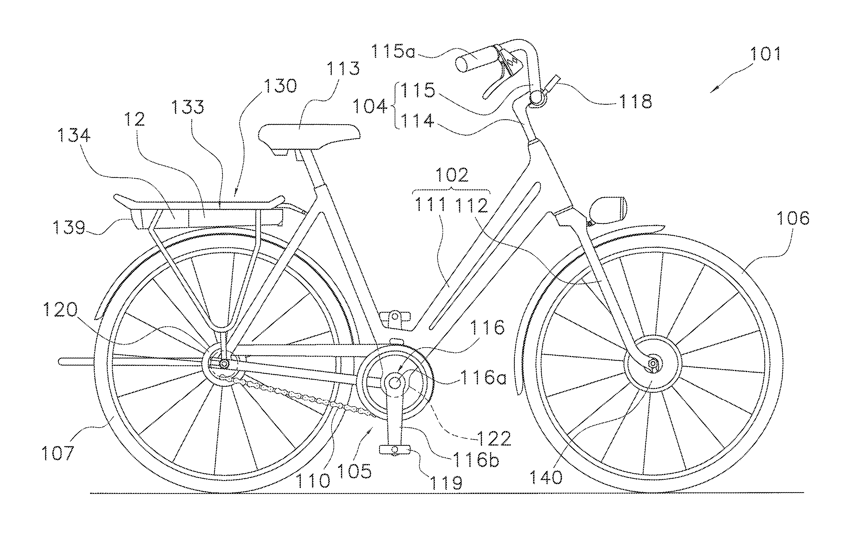
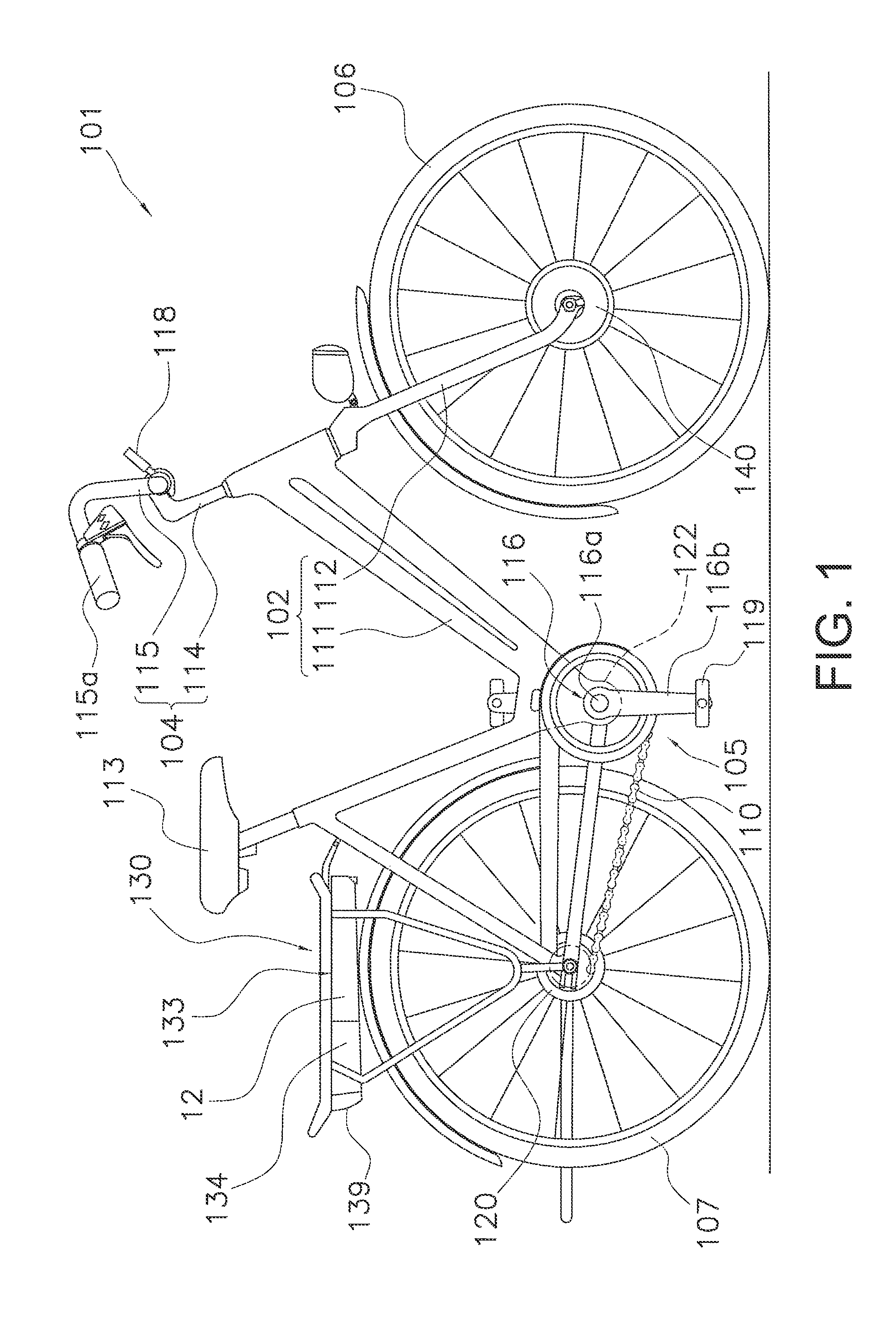
[0036]FIG. 1 shows a bicycle 101 that employs a bicycle control apparatus according to a The bicycle 101 comprises chiefly a frame 102, a handlebar unit 104, a display device 124, a front wheel 106, a rear wheel 107, a chain 110, a crank 116, an internal transmission 120, a rear carrier 130, a rechargeable battery 134, an assistance motor unit 140, a controller 117 that constitutes a part of the bicycle control apparatus, and a front brake device and a rear brake device that are not shown in the drawings. The chain 110, the crank 116, the controller 117, the internal transmission 120 and the assistance motor unit 140 are parts of a bicycle drive system of the bicycle 101 for propelling the bicycle 101.

[0037]The frame 102 has a frame body 111 and a front fork 112. The front fork 112 is attached to a frontward portion of the frame body 111 such that it can pivot about a slanted axis. A saddle 94, the handlebar unit 104, and other components are attached to frame 102.

[0038]The crank 1...

second embodiment

[0065]FIG. 6 shows a bicycle 201 that employs a bicycle control apparatus according to the The bicycle 201 comprises chiefly a frame 202, a handlebar unit 204, a display device 224, a front wheel 206, a rear wheel 207, a chain 210, a crank 216, an external transmission 220, a rear carrier 230, a rechargeable battery 234, an assistance motor unit 240, a controller 217 that constitutes a part of bicycle control apparatus, and a front brake device and a rear brake device that are not shown in the drawings.

[0066]The frame 202, the crank 216, the handlebar unit 204, the rear carrier 230, the assistance motor unit 240, the pedaling three sensor 195, and the display device 224 are basically the same as in the first embodiment. Therefore, the reference numerals of these parts shown in FIGS. 6 and 7 are the reference numerals of the first embodiment with 100 added thereto and explanations of these parts are omitted. Meanwhile, the front fork 212 is provided with a suspension function. Also,...


PUM


Abstract

A bicycle control apparatus is configured to control a bicycle having a transmission and a drive assistance electric motor that drives a wheel. The bicycle control apparatus includes a pedaling force detector and a controller. The pedaling force detector detects a pedaling force. The controller includes a control section that controls the drive assistance electric motor according to a pedaling force detected by the pedaling force detector. The control section increases a ratio of an output of the drive assistance electric motor with respect to the pedaling force upon completion of a downshift of the transmission, and subsequently decreasing the ratio of the output of the drive assistance electric motor with respect to the pedaling force.

Description

CROSS-REFERENCE TO RELATED APPLICATIONS[0001]This application claims priority under 35 U.S.C. §119 to Japanese Patent Application No. 2012-087075, filed Apr. 6, 2012. The entire disclosure of Japanese Patent Application No. 2012-087075 is hereby incorporated herein by reference.BACKGROUND[0002]1. Field of the Invention[0003]This invention generally relates to a bicycle control apparatus that controls a bicycle having a transmission and an electric motor for drive assistance.[0004]2. Background Information[0005]Electrically assisted bicycles that assist riding by supplementing a person's pedaling force with a motor drive force are becoming popular. Japanese Laid-Open Patent Publication No. 9-58569 discloses an electrically assisted bicycle equipped with a transmission. With this bicycle, a force exerted against a pedal by a person is transmitted through a chain to the transmission, modified according to the gear ratio of the transmission, and then transmitted to a rear wheel. The bic...

Claims


Application Information

Patent Timeline
Patent Type & Authority Patents(United States)
IPC IPC(8): B60K1/02B62M6/50
CPCB60W20/10B62M6/50B62M25/08
Inventor TAKACHI, TAKESHI
Owner SHIMANO INC
Learn More