Wideband antenna

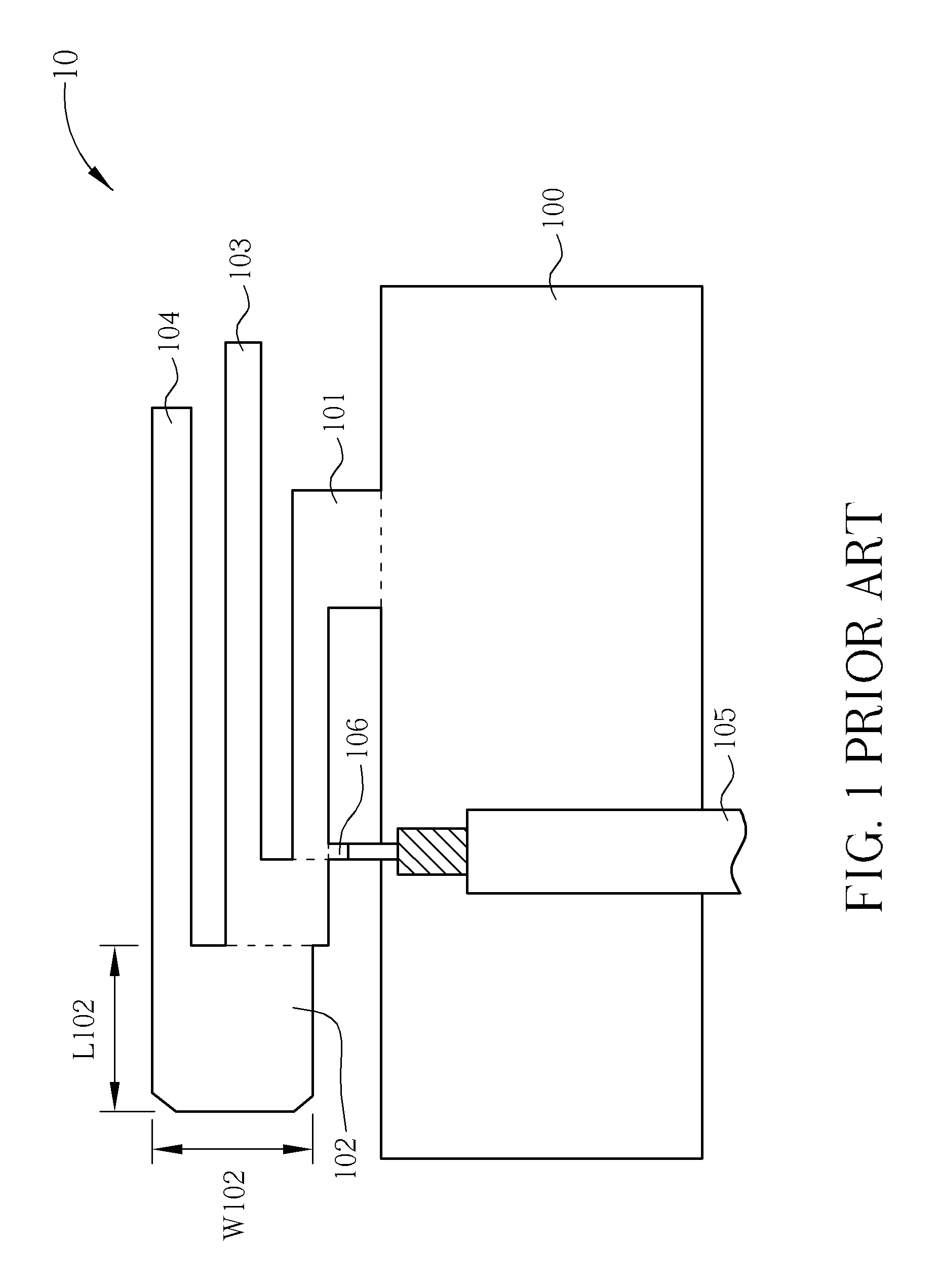
a wideband antenna and antenna earthing technology, applied in the direction of resonant antennas, antenna earthings, elongated active element feeds, etc., can solve the problem that multi-band antennas b>10/b> thus fail to meet different users' requirements

Active Publication Date: 2014-07-15
WISTRON NEWEB
View PDF11 Cites 15 Cited by
  • Summary
  • Abstract
  • Description
  • Claims
  • Application Information

AI Technical Summary

Problems solved by technology

However, with the advance of wireless communication technology, a wider operational band of the wireless communication system is anticipated, and the multi-band antenna 10 thus fails to satisfy different users' requirements.
Therefore, it has become an important issue to provide an antenna which can effectively extend the transmitting band as well as minimize the physical dimension of the antenna.

Method used


Image

  • Wideband antenna
  • Wideband antenna
  • Wideband antenna

Examples


Embodiment Construction

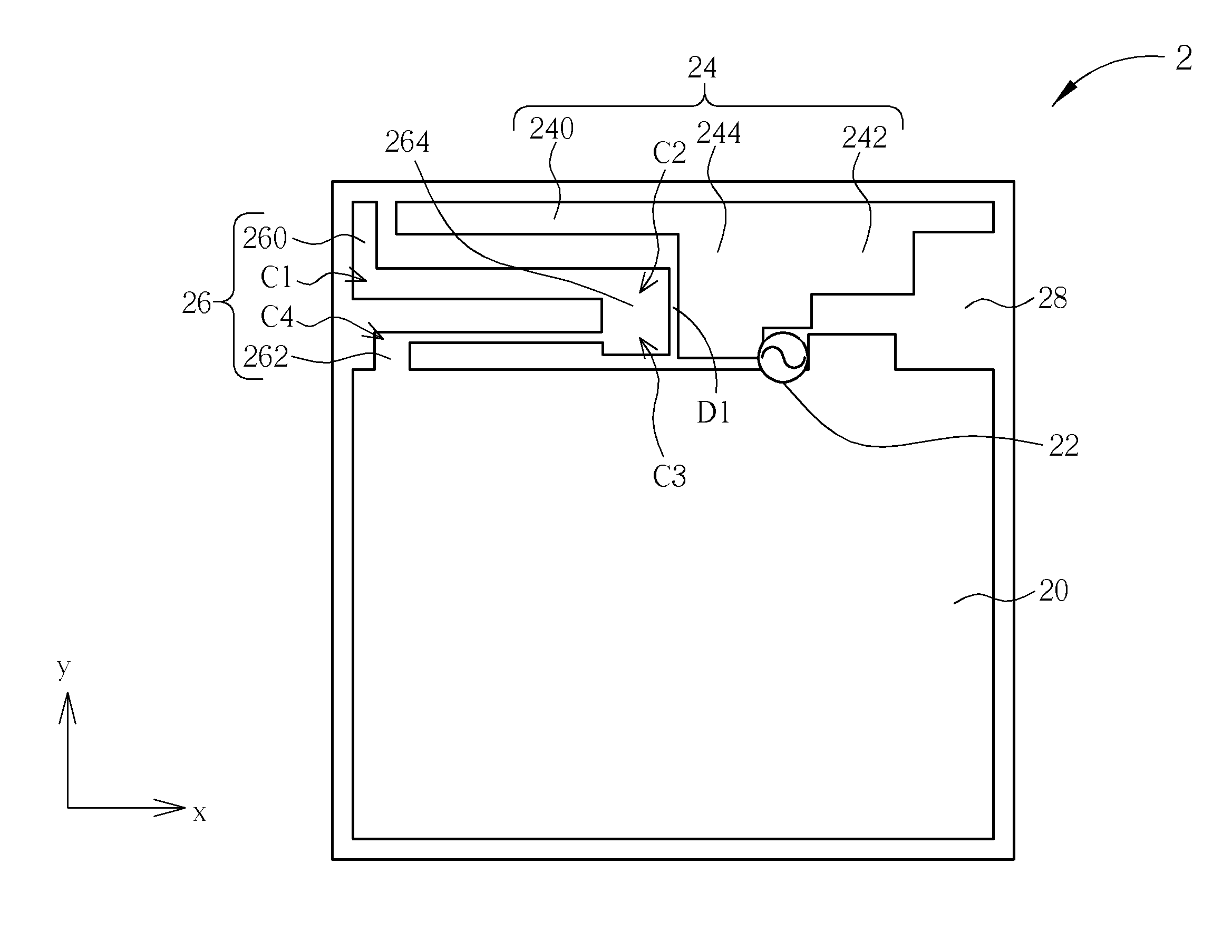
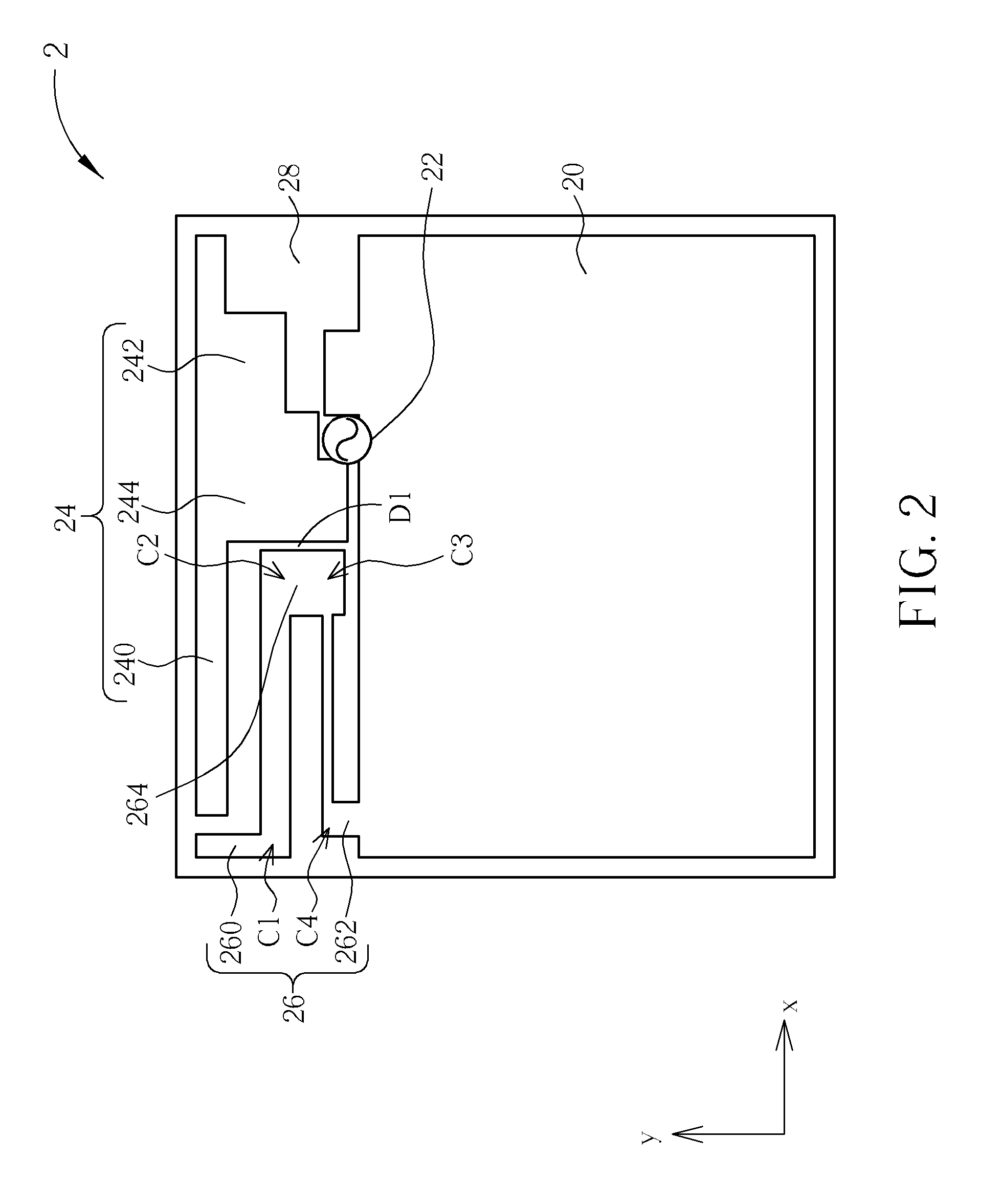
[0019]Please refer to FIG. 2, which illustrates a schematic diagram of a wideband antenna 2 according to an embodiment of the invention. As shown in FIG. 2, the wideband antenna 2 is located on an X-Y plane including an X-axis direction perpendicular to a Y-axis direction. The wideband antenna 2 loaded by a substrate 28 includes a grounding unit 20, a feed-in source 22, a first radiating body 24 and a second radiating body 26. The first radiating body 24 is utilized to transmit a high frequency band, and a total length of the first radiating body 24 is approximately equal to one fourth wavelength of the high frequency band. The first radiating body 24 further includes a first radiating unit 240, a second radiating unit 242 and a conducting unit 244. The first radiating unit 240 and the second radiating unit 242 both extend along the X-axis direction, and the conducting unit 244 horizontally connects the first radiating unit 240 and the second radiating unit 242, which means that the...


PUM


Abstract

A wideband antenna includes a grounding unit electrically connected to a ground, a feed-in source for transmitting and receiving radio frequency signals, a first radiating body including a first radiating unit extending along a first direction, a second radiating unit extending along a second direction opposite to the first direction, and a conducting unit extending along a third direction, and a second radiating body including a short-circuit unit electrically connected to the grounding unit, a third radiating unit including a branch to generate a coupling connection effect with the conducting unit via a first distance, wherein an average perpendicular distance between the second radiating body and the grounding unit is smaller than an average perpendicular distance between the first radiating body and the grounding unit.

Description

RELATED APPLICATIONS[0001]This application claims priority under 35 U.S.C. 119 from TAIWAN 101104315 filed Feb. 10, 2012, the contents of which are incorporated herein by references.BACKGROUND OF THE INVENTION[0002]1. Field of the Invention[0003]The present invention relates to a wideband antenna, and more particularly, to a wideband antenna which utilizes a vertical coupling connection effect.[0004]2. Description of the Prior Art[0005]An electronic product with a wireless communication function, e.g. a laptop, a personal digital assistant, etc., utilizes an antenna to emit or receive radio waves, to transmit or exchange radio signals, so as to access a wireless network. Therefore, to facilitate a user's access to the wireless communication network, an ideal antenna should maximize its bandwidth within a permitted range, while minimizing physical dimensions to accommodate the trend for smaller-sized electronic products.[0006]In the prior art, e.g. publication number I318022 of Taiwa...

Claims


Application Information

Patent Timeline
Patent Type & Authority Patents(United States)
IPC IPC(8): H01Q5/10H01Q1/48H01Q1/38
CPCH01Q1/2266H01Q9/42H01Q13/10H01Q1/48
Inventor HUANG, KUO-LUNCHIANG, YU-YUTSENG, SHANG-CHING
Owner WISTRON NEWEB
Why Eureka
Try Eureka