
Paper used in an inkjet printer, inkjet printer, and preliminary ejection method for an inkjet printer

a technology of inkjet printer and inkjet paper, which is applied in the direction of printing, typewriters, duplicating/marking methods, etc., can solve the problems of ink taking longer to dry, recording paper and parts along the conveyance path can become soiled, and unsatisfactory appearance, so as to maintain the appearance of recording parts and reduce the soiling of inkjet paper

Active Publication Date: 2014-07-22
SEIKO EPSON CORP
View PDF15 Cites 0 Cited by
  • Summary
  • Abstract
  • Description
  • Claims
  • Application Information

AI Technical Summary

Benefits of technology

[0014]Inkjet paper according to the invention has an open part with a length that covers the length of the recording area, that is, the area to which the inkjet head of the inkjet printer can eject ink, in the direction perpendicular to the conveyance direction in which the paper is conveyed in the inkjet printer, that is, across the width of continuous inkjet paper. As a result, the inkjet head can flush ink through this open part. The flushed ink can therefore be prevented from landing on the surface of the continuous inkjet paper. The appearance of the recording area of the continuous inkjet paper can therefore be maintained, and soiling of the continuous inkjet paper and area around the paper feed path can be reduced.
[0016]The continuous length of the open part across the paper width can thus be reduced in the inkjet paper according to this aspect of the invention. A loss of rigidity in the inkjet paper can therefore be prevented. As a result, stable conveyance of the inkjet paper can be maintained while ink can be flushed through these openings. The flushed ink can therefore be prevented from landing on the surface of the inkjet paper.
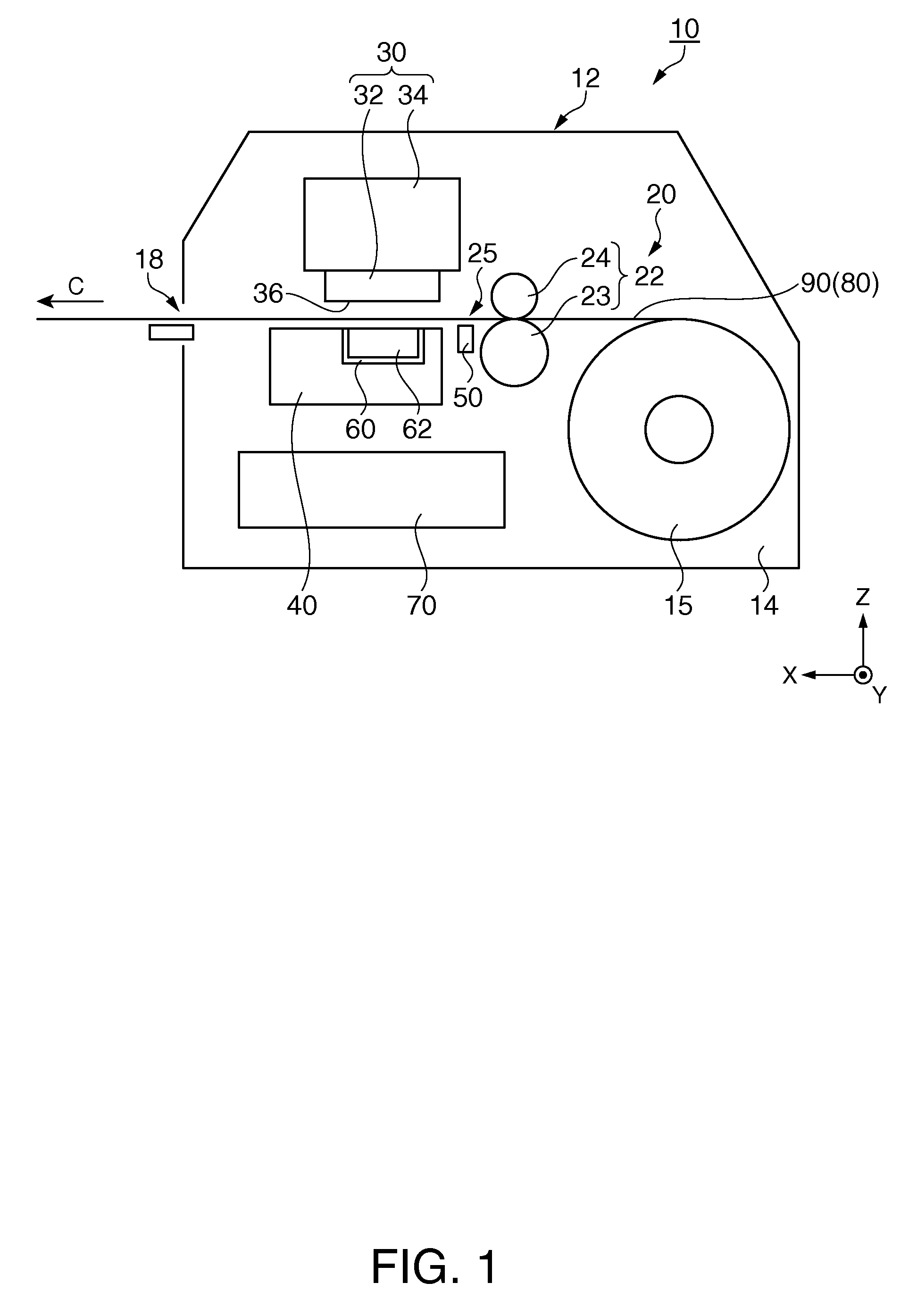
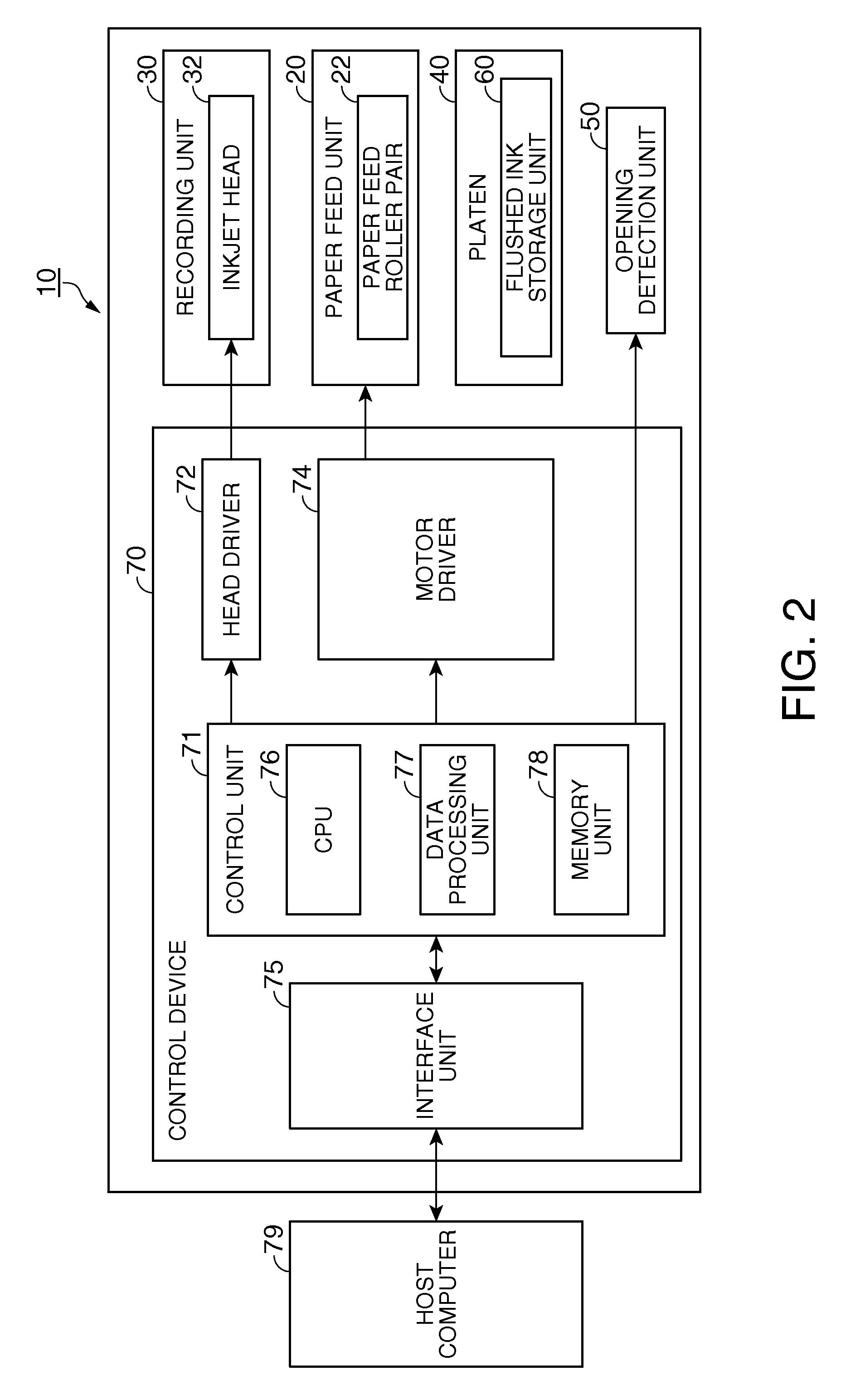
[0026]The open part detection unit of the inkjet printer according to this aspect of the invention can detect the position of the open part of the inkjet paper conveyed by the paper feed unit. Ink can also be ejected from the inkjet head through the open part into a waste ink storage unit disposed at a position opposite the inkjet head with the paper feed path therebetween to flush the inkjet head. The inkjet head can therefore be flushed when inkjet paper is in the paper feed path while preventing the flushed waste ink from landing on the surface of the inkjet paper. The inkjet printer can therefore maintain the appearance of the recording part of the inkjet paper, and reduce soiling of the inkjet paper and the area around the paper feed path.
[0029]With this method, the inkjet printer can detect the position of the open part of the inkjet paper conveyed in the paper feed step in the open part detection step. Ink can also be ejected from the inkjet head through the open part into a waste ink storage unit disposed at a position opposite the inkjet head with the paper feed path therebetween to flush the inkjet head. The inkjet head can therefore be flushed when inkjet paper is in the paper feed path while preventing the flushed waste ink from landing on the surface of the inkjet paper. The inkjet printer can therefore maintain the appearance of the recording part of the inkjet paper, and reduce soiling of the inkjet paper and the area around the paper feed path.

Problems solved by technology

A problem with this type of inkjet printer, however, is that an unnecessary pattern is recorded on the recording paper, resulting in an undesirable appearance.
In addition, because a concentrated amount of ink is ejected to eliminate the causes of ejection problems, the ink takes longer to dry than normal text and images, and the recording paper and parts along the conveyance path can become soiled.
This exacerbates the problem.

Method used


Image

  • Paper used in an inkjet printer, inkjet printer, and preliminary ejection method for an inkjet printer
  • Paper used in an inkjet printer, inkjet printer, and preliminary ejection method for an inkjet printer
  • Paper used in an inkjet printer, inkjet printer, and preliminary ejection method for an inkjet printer

Examples


embodiment 1

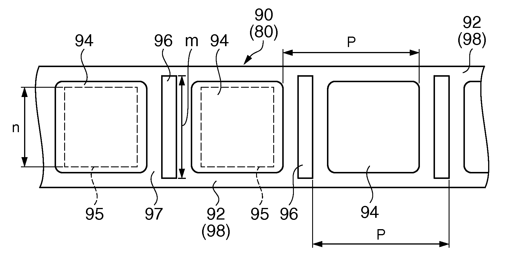
[0055]Inkjet paper 80 according to a first embodiment of the invention is described below with reference to FIG. 3. FIG. 3 shows an example of inkjet paper 80 according to the first embodiment of the invention, and more specifically shows an example of label paper. FIG. 3A is a plan view from the label side, and FIG. 3B is a section view of the label paper. An embodiment using this label paper as the inkjet paper 80 is described below.

[0056]As shown in FIG. 3, the label paper 90 used as the inkjet paper 80 has a liner 92 and labels 94. The labels 94 are rectangular with an adhesive coating on the back side. The front of each label 94 is the recording area 95 where the printer 10 records information. The labels 94 are affixed continuously at a specific pitch P along the length (second direction) of one side of the liner 92.

[0057]The liner 92 is a continuous web with a specific width in the first direction, and has a coating 98 on one side 92a that facilitates peeling the labels 94 fr...


PUM

PropertyMeasurementUnit
areaaaaaaaaaaa
viscosityaaaaaaaaaa
speedaaaaaaaaaa

Abstract

An inkjet printer includes an inkjet head having a nozzle to eject ink in a first direction for recording information. A platen that has an ink storage unit for storing the ink ejected from the nozzle. The platen is opposite the inkjet head and configured to guide paper formed with an open part. A paper feed unit is provided in the inkjet printer and is configured to convey the paper in a second direction cross to the first direction, and to move the paper over the platen. A print control unit is further provided in the inkjet printer and is configured to cause the nozzle to eject ink into the ink storage unit when the open part of the paper is conveyed to a position opposite the inkjet head.

Description

BACKGROUND[0001]1.Technical Field[0002]The present invention relates to paper that is used in an inkjet printer to record information, to an inkjet printer, and to a preliminary ejection method for an inkjet printer.[0003]2.Related Art[0004]Inkjet printers eject ink as droplets from plural nozzles in an inkjet head to record information on recording paper. If an inkjet printer is not used for a certain period of time, air bubbles can form in the nozzles and the viscosity of the ink can increase. Foreign matter such as paper dust from the recording paper can also collect around the nozzles. As a result, some inkjet printers eject ink at specific times to eliminate such causes of ink ejection problems. This operation is called preliminary ejection or flushing.[0005]Serial inkjet printers in which the inkjet head moves perpendicularly to the conveyance direction of the recording paper, and inkjet printers that record information on cut-sheet paper, perform the preliminary ejection oper...

Claims


Application Information

Patent Timeline
Patent Type & Authority Patents(United States)
IPC IPC(8): B41J2/01B41J29/38
CPCB41J2/215B41J2/16526B41J2/16585B41M5/502
Inventor ITO, KIYOSHIKOBAYASHI, NAOKI
Owner SEIKO EPSON CORP
Learn More