Implant for stabilizing vertebrae or bones
a technology for stabilizing implants and vertebrae, applied in joint implants, internal osteosynthesis, medical science, etc., can solve the problems of vascular structure beyond the vertebral end plates being damaged, discomfort or pain, and the portion of bone cement exiting the vertebral body and flowing, so as to reduce the risk of neighbouring vertebrae being fractured, the long-term effect of treatment improvemen
- Summary
- Abstract
- Description
- Claims
- Application Information
AI Technical Summary
Benefits of technology
Problems solved by technology
Method used
Image

Examples
first embodiment
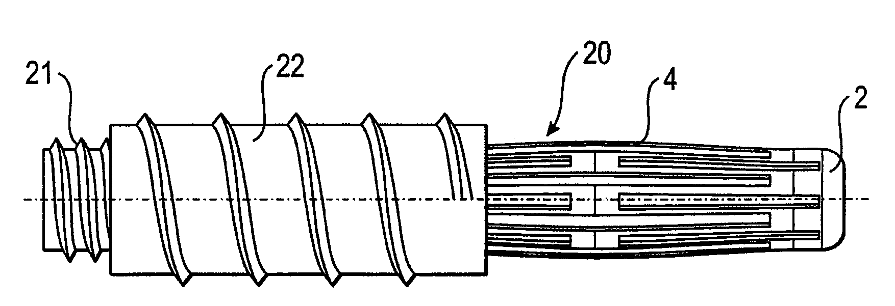
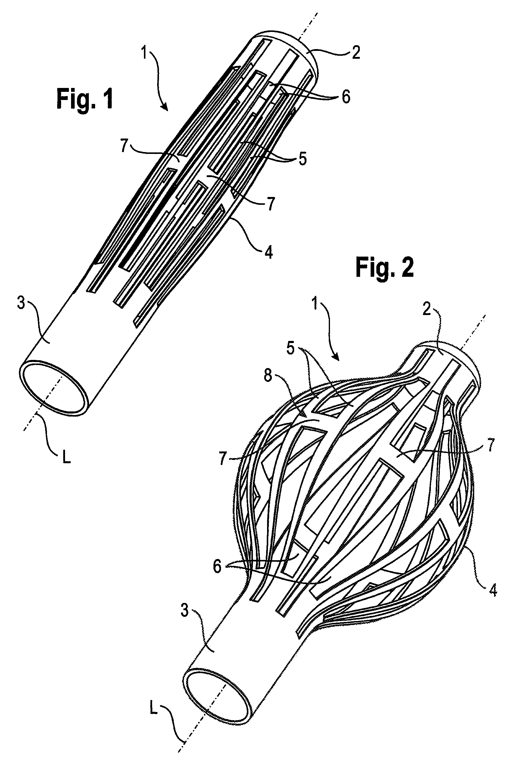
[0024]the implant is described with reference to FIGS. 1 and 2. The implant 1 is tubular with a longitudinal axis L and includes a first end section 2 and a second end section 3 and an intermediate section 4. The intermediate section 4 includes of a plurality of longitudinal strips 5 extending from the first end section 2 to the second end section 3. There are gaps or slots 6 between the longitudinal strips 5 which also extend from the first end section 2 to the second end section 3. Pairs of longitudinal strips 5 are connected to each other approximately at their center when seen in the longitudinal direction via a transverse strip 7, respectively. Hence, two longitudinal strips 5 and the connecting transverse strip 7 form a strip unit 8. As can be seen, every second of the slots 6 extends further into the tubular end sections 2 and 3. The strips 5 provide flexibility to the intermediate section 4 in such a manner that as shown in FIG. 2, the intermediate section 4 can be expanded ...
embodiment 1
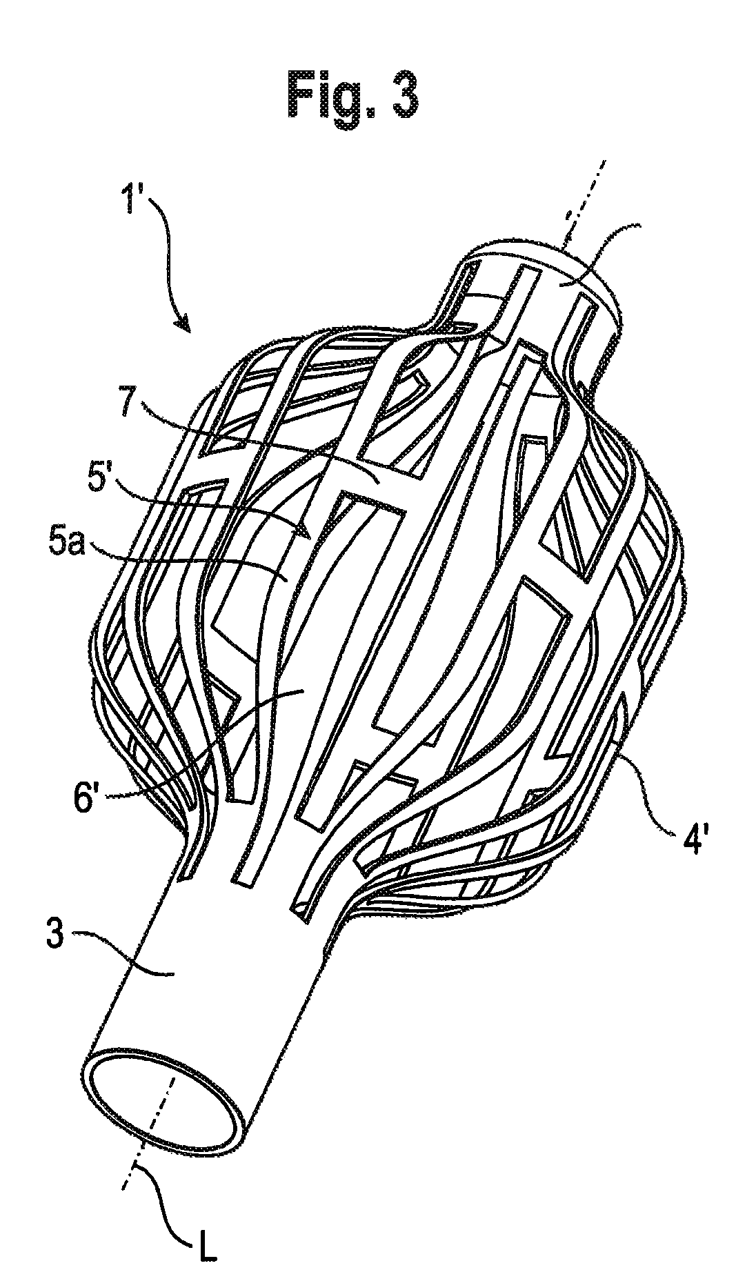
[0028]FIG. 3 shows a perspective view of a modified embodiment 1′ of the implant which differs from the implant 1 shown in FIGS. 1 and 2 by the shape of the expanded intermediate section 4′. The other parts are identical and therefore, the description thereof is not repeated. While the intermediate section 4 shown in FIG. 2 has approximately a spherical or ellipsoidal shape, the intermediate section 4′ of the implant 1′ in FIG. 3 comprises flat portions 5a′ of strips 5′ extending in parallel to the longitudinal axis L. The strips 5′ are shaped in such a way that when expanding the intermediate section 4′ it forms an approximately polygonal shape which tapers towards the first end section 2 and to the second end section 3.
[0029]It should be noted that any desired shape of the expanded intermediate section 4 can be achieved by designing the pattern of longitudinal and transverse strips in a suitable manner. For example, it is possible to design the intermediate section 4 as a pattern ...
second embodiment
[0032]The second embodiment is useful for such cases where it is not possible to provide a stop at the proximal first end section 2.
[0033]Use of the implant is now explained with reference to FIGS. 8 to 11. FIGS. 8 to 10 show schematic views of a vertebra 100 from the top and FIG. 11 from the side. The vertebral body 101 is damaged (not shown), for example, by osteoporosis or by a fracture. First, as shown in FIG. 8 a hole 102 is prepared in the pedicle of vertebra 100, the hole reaching the damaged inner vertebral body 101. The implant 1 is inserted into the hole and, as shown in FIG. 9, pushed into the vertebral body 101 until the end section 2 abuts against the inner wall, which forms a stop 9 for the implant. When pushing the implant 1 against stop 9 the intermediate section 4 expands into the vertebral body. As can be seen in FIG. 11 the expanded implant which is compressible to some extent in the region of its intermediate section 4 forms a flexible support for the end plate 1...
PUM
 Abstract
Description
Claims
Application Information
 - R&D
- Intellectual Property
- Life Sciences
- Materials
- Tech Scout
- Unparalleled Data Quality
- Higher Quality Content
- 60% Fewer Hallucinations
Browse by: Latest US Patents, China's latest patents, Technical Efficacy Thesaurus, Application Domain, Technology Topic, Popular Technical Reports.
© 2025 PatSnap. All rights reserved.Legal|Privacy policy|Modern Slavery Act Transparency Statement|Sitemap|About US| Contact US: help@patsnap.com