Solid-state image pickup device, imaging device, and dispersing element

a solid-state image and imaging device technology, applied in the field of dispersing elements, can solve the problems of increasing the light receiving efficiency, the device cannot be applied to the dispersing element, and the amount of incident light is reduced, so as to achieve favorable image with stability, efficiently disperse backlight to different display pixels, and improve light utilization efficiency

Inactive Publication Date: 2014-07-29
PANASONIC CORP
View PDF20 Cites 1 Cited by
  • Summary
  • Abstract
  • Description
  • Claims
  • Application Information

AI Technical Summary

Benefits of technology

[0017]According to the solid-state image pickup device of the present invention, an incident light beam is dispersed into light beams of component wavelength bands, and the respective light beams are guided to the corresponding light receiving regions for photoelectric conversion. Therefore, the light utilization efficiency is improved as compared with the conventional method using color filters. Further, by using this solid-state image pickup device, the imaging device of the present invention can take a favorable image with stability even in low illumination environment.
[0018]Further, the dispersing element of the present invention can spatially disperse an incident light beam to predetermined places according to its wavelength bands. Therefore, when the dispersing element is used in a liquid crystal display device or the like, the dispersing element can efficiently disperse backlight to different display pixels. Therefore, even if the intensity of the backlight is low, a bright display screen can be obtained, which contributes to power saving of the device.

Problems solved by technology

However, the solid-state image pickup device disclosed in Japanese Laid-Open Patent Publication No. 2008-71920 has a problem that the loss due to the color filters causes reduction in the amount of incident light.
However, since the light, other than the light of the selected wavelength incident on each pixel, is reflected, increase in the light receiving efficiency cannot be expected.
Therefore, the dispersing element is not expected to be applied to devices other than the 3-CCD imaging device having a relatively high degree of freedom in arrangement of the solid-state image pickup devices.

Method used


Image

  • Solid-state image pickup device, imaging device, and dispersing element
  • Solid-state image pickup device, imaging device, and dispersing element
  • Solid-state image pickup device, imaging device, and dispersing element

Examples


embodiment 1

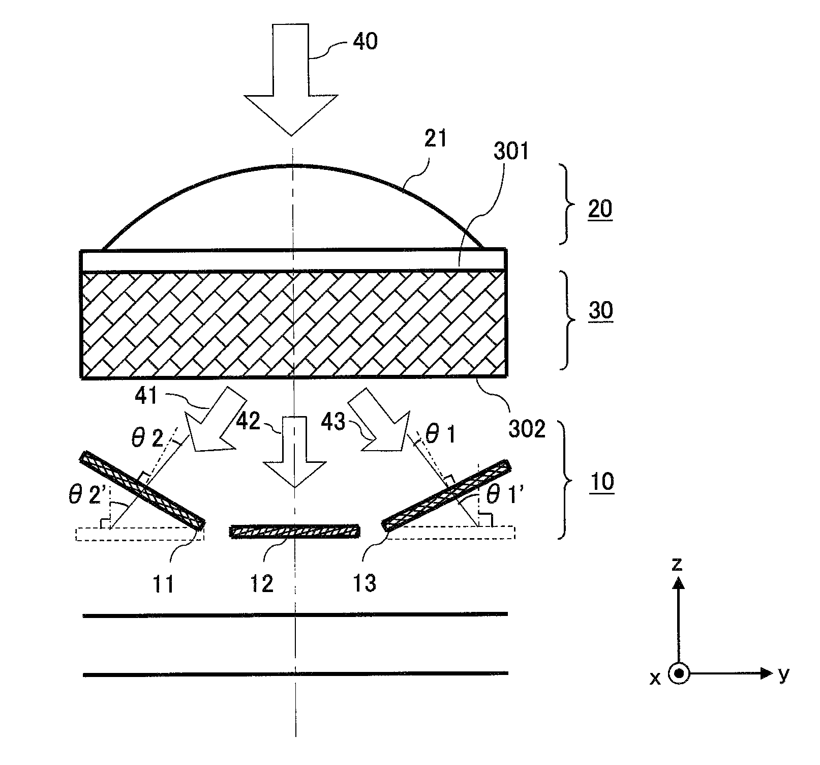
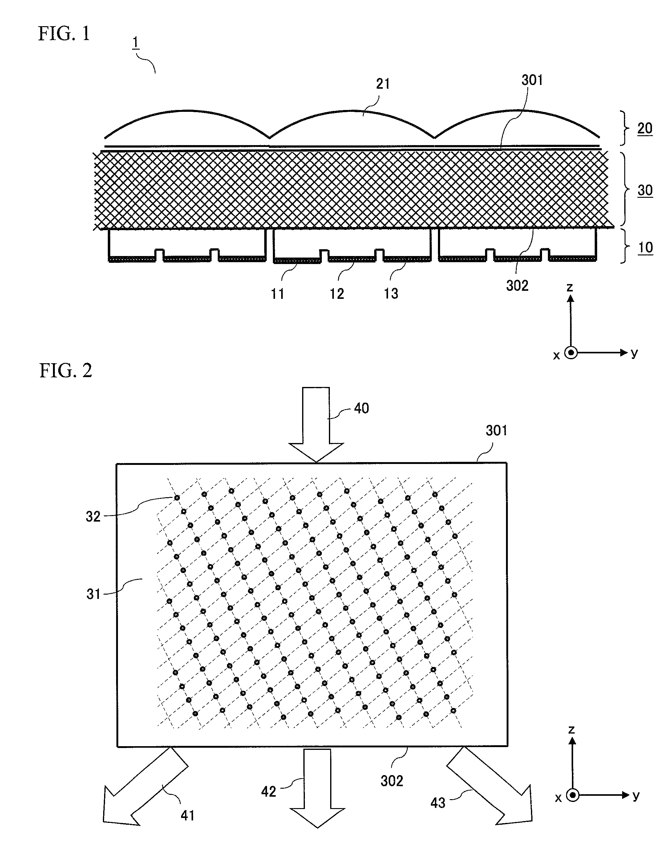
[0035]FIG. 1 is a schematic configuration diagram illustrating a solid-state image pickup device according to a first embodiment. The solid-state image pickup device 1 mainly includes a photoelectric conversion unit 10 formed on a semiconductor substrate, a lens unit 20, and a dispersing element 30.

[0036]The photoelectric conversion unit 10 includes a plurality of light receiving regions two-dimensionally arrayed on an xy plane in FIG. 1. The photoelectric conversion unit 10 performs photoelectric conversion of light incident on each light receiving region, and outputs an electric signal according to the intensity of the incident light. More specifically, the photoelectric conversion unit 10 includes light receiving regions 11 for detecting green light, light receiving regions 12 for detecting red light, and light receiving regions 13 for detecting blue light. In the present embodiment, the light receiving regions 11, 12, and 13 are repeatedly arranged in this order. The electric si...

embodiment 2

[0051]FIG. 7 is a schematic configuration diagram illustrating a solid-state image pickup device according to a second embodiment. The following will mainly describe the difference between the present embodiment and the first embodiment.

[0052]In the first embodiment, the red light receiving region 12, the green light receiving region 11, and the blue light receiving region 13 have approximately the same area. In this case, the light receiving area for green light is reduced as compared to a solid-state image pickup device having ordinary RGB Bayer color filters.

[0053]So, in the present embodiment, the light receiving region 11 is increased relative to the light receiving regions 12 and 13 to increase the ratio of the light receiving area for green light. Thus, by varying the area of the light receiving region according to the colors, the balance among the amounts of the received beams of the respective colors can be appropriately set.

[0054]In the present embodiment, in order to incr...

embodiment 3

[0055]FIG. 8 is a schematic configuration diagram illustrating a solid-state image pickup device according to a third embodiment. The following will mainly describe the difference between the present embodiment and the first embodiment.

[0056]In the present embodiment, the light receiving surfaces of the green light receiving region 11 and the blue light receiving region 13 are inclined with respect to the incident surface of the dispersing element 30. Specifically, the light receiving surface of the light receiving region 13 is inclined so that an angle θ1 formed between the normal line of the light receiving surface of the light receiving region 13 and the light transmitted through the dispersing element 30 is smaller than an angle θ1′ in the case where the light receiving surface is not inclined. Likewise, the light receiving surface of the light receiving region 11 is inclined so that an angle θ2 formed between the normal line of the light receiving surface of the light receiving...


PUM


Abstract

A solid-state image pickup device capable of taking more light into light receiving regions is provided. The solid-state image pickup device of the present invention includes: a photoelectric conversion unit having a plurality of light receiving regions that are two-dimensionally arrayed, the photoelectric conversion unit for photoelectrically converting light incident on each of the light receiving regions, and outputting an electric signal according to the intensity of the incident light; a lens unit comprising a plurality of converging lenses provided on an upper layer of the photoelectric conversion unit, each of the converging lens being provided corresponding to a set of continuous first to third light receiving regions; and a dispersing element provided between the photoelectric conversion unit and the lens unit, the dispersing element being formed of a medium whose refractive index varies periodically, and diffracting beams of a first wavelength band and of a third wavelength band, having been transmitted through the converging lens, and directing the beams onto the first light receiving region and the third light receiving region, and transmitting, without diffracting, a beam of a second wavelength band, having been transmitted through the converging lens, and directing the beam onto the second light receiving region.

Description

CROSS REFERENCE TO RELATED APPLICATION[0001]The disclosure of Japanese Patent Application No. 2010-000954, filed Jan. 6, 2010, is incorporated herein by reference.BACKGROUND OF THE INVENTION[0002]1. Field of the Invention[0003]The present invention relates to dispersing elements for dispersing incident light into different wavelength bands. In addition, the present invention relates to solid-state image pickup devices, and imaging devices such as digital cameras, employing the dispersing element.[0004]2. Description of the Background Art[0005]With the spread of digital cameras, solid-state image sensors such as CCD image sensors and CMOS image sensors have been widely used. A solid-state image sensor has a plurality of light receiving regions on a light receiving surface, and converts light incident on each region into an electric signal according to the intensity of the incident light, thereby generating image information.[0006]In the digital camera market, reduction in device size...

Claims


Application Information

Patent Timeline
Patent Type & Authority Patents(United States)
IPC IPC(8): H04N9/04H01L27/00H04N5/225H04N9/097
CPCH01L27/14629G02B5/18H01L27/14627
Inventor YAMAGATA, MICHIHIROTANAKA, YASUHIROYAMADA, KAZUHIROITOH, KAZUYOSHIOZEKI, YASUYUKI
Owner PANASONIC CORP
Why Eureka
Try Eureka