
Tomographic reconstruction of a moving object

a moving object and reconstruction technology, applied in tomography, applications, instruments, etc., can solve the problems of inability to have exact prior knowledge of the motion m, and the problem of not uniformly solving the problem of bias

Active Publication Date: 2014-07-29
GENERAL ELECTRIC CO
View PDF3 Cites 5 Cited by
  • Summary
  • Abstract
  • Description
  • Claims
  • Application Information

AI Technical Summary

Benefits of technology

The invention relates to a method and system for reconstructing a 3D image of a moving object using 2D images obtained from a medical imaging system. The technical effect of the invention is to reduce the error in the reconstructed image caused by motion and to improve the quality of the image using an approximate model of the object's motion.

Problems solved by technology

That in general there exists an approximation error g*(λ)−f, itself proportional to λ (it will be said that the solution is biased, however this bias is not uniform on the solution).
In addition, that in general it is not possible to have exact prior knowledge of the motion M={M(t1), .

Method used


Image

  • Tomographic reconstruction of a moving object
  • Tomographic reconstruction of a moving object
  • Tomographic reconstruction of a moving object

Examples


Embodiment Construction

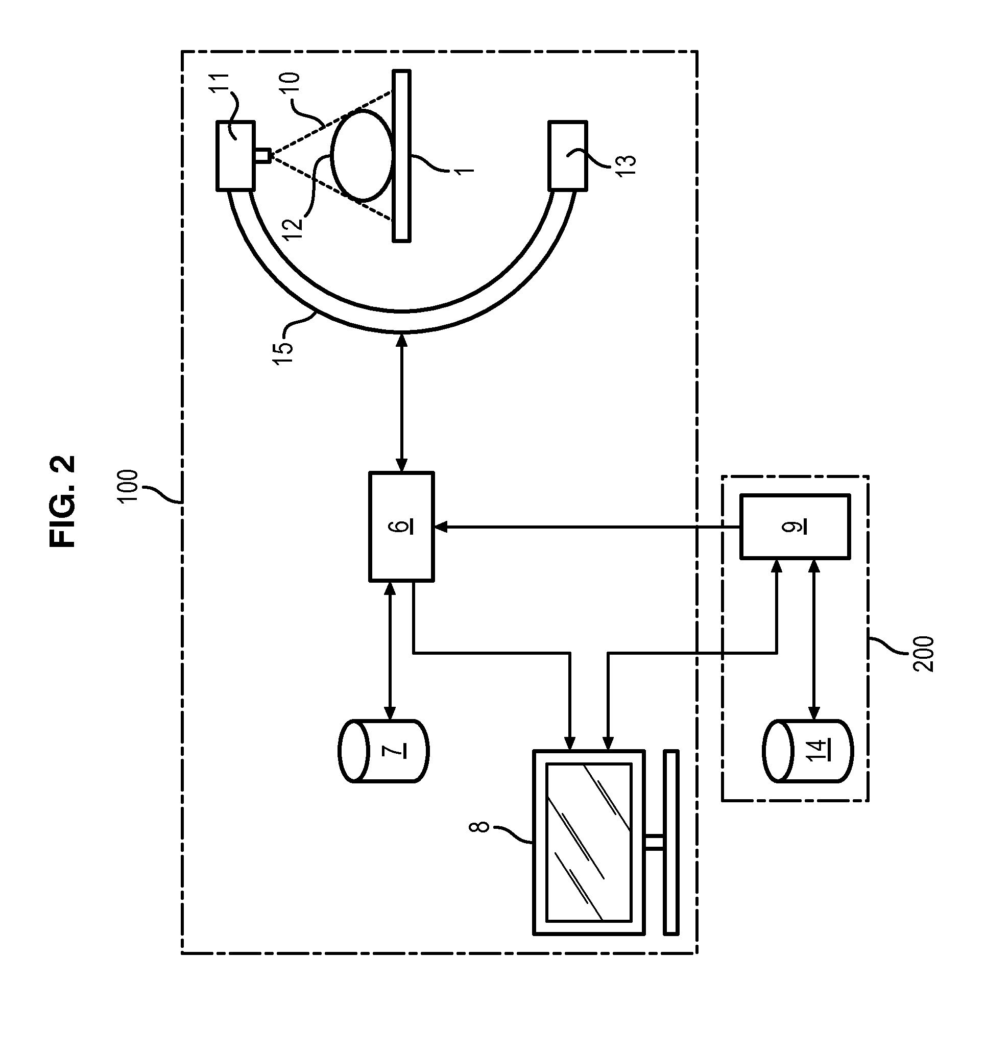
[0028]FIG. 2 schematically illustrates a medical imaging system 100 to acquire 2D projection images for the reconstruction of a 3D image of an object such as an organ. The system may be used for the detection and characterization of stenosis in vessels. The medical imaging system 100 comprises: a support 1 intended to receive a patient (not illustrated) to be examined, in whom it is desired to image an organ 12; a source 11 intended to emit an X-ray beam 10; a detector 13 arranged facing the source 11 and configured to detect the X-rays emitted by the) source 11; a control unit 6; a storage unit 7; and a display unit 8. The X-ray source 11 and the detector 13 are connected by means of a C-arm 15, for example.

[0029]The detector 13 may be a semiconductor image sensor, for example comprising caesium iodide phosphor (scintillator) on a transistor / amorphous silicon photodiode array. Other suitable detectors are: a CCD sensor or a direct digital detector which directly converts X-rays int...


PUM


Abstract

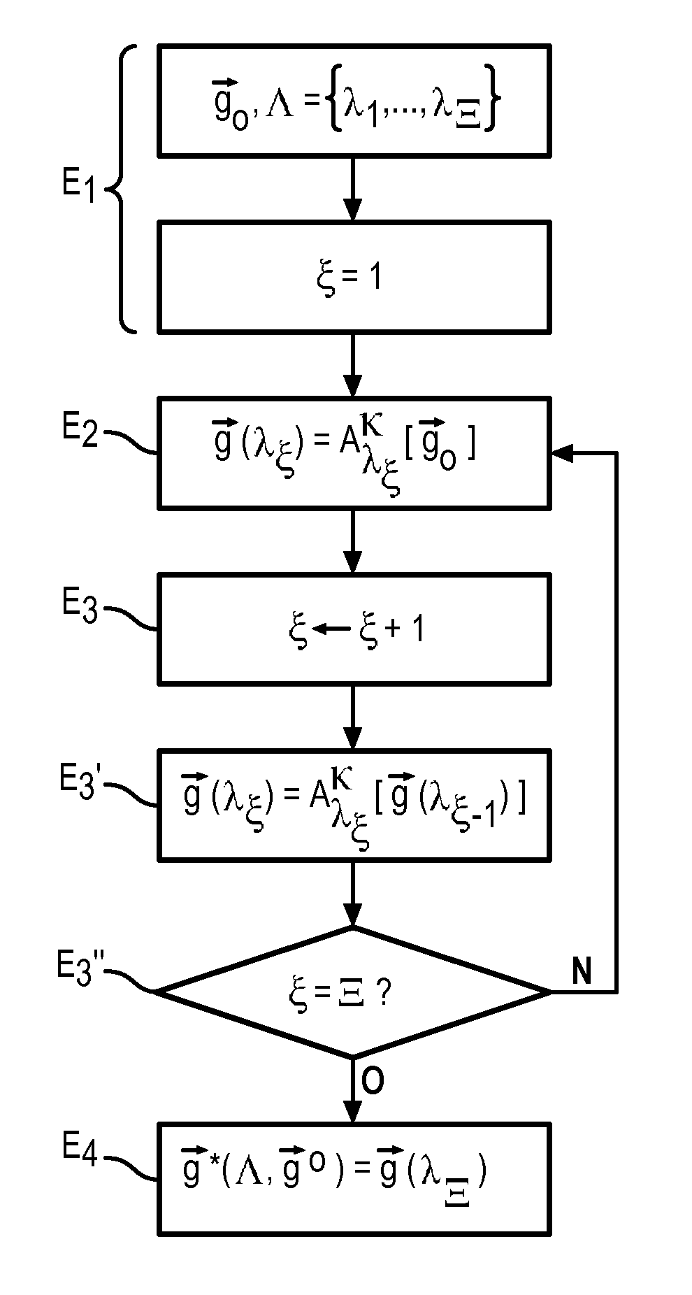
A method is provided for processing a sequence of sets of 2D projection images of a moving object, wherein the sequence of sets of 2D projection images is obtained by a medical imaging system that is in motion along a trajectory. The method comprises determining a sequence of images which minimize a function dependant on a set of 3D images, a term of fidelity of the sequence of images, a function of spatial and temporal compression of the sequence of images, a compressibility parameter, and a sequence of operators for an approximate modelling of motion. The sequence of operators leads to a compression constraint augmented by partial knowledge of the motion and the minimization comprises defining a decreasing sequence of degrees of compressibility for which an estimation is determined from an initial sequence.

Description

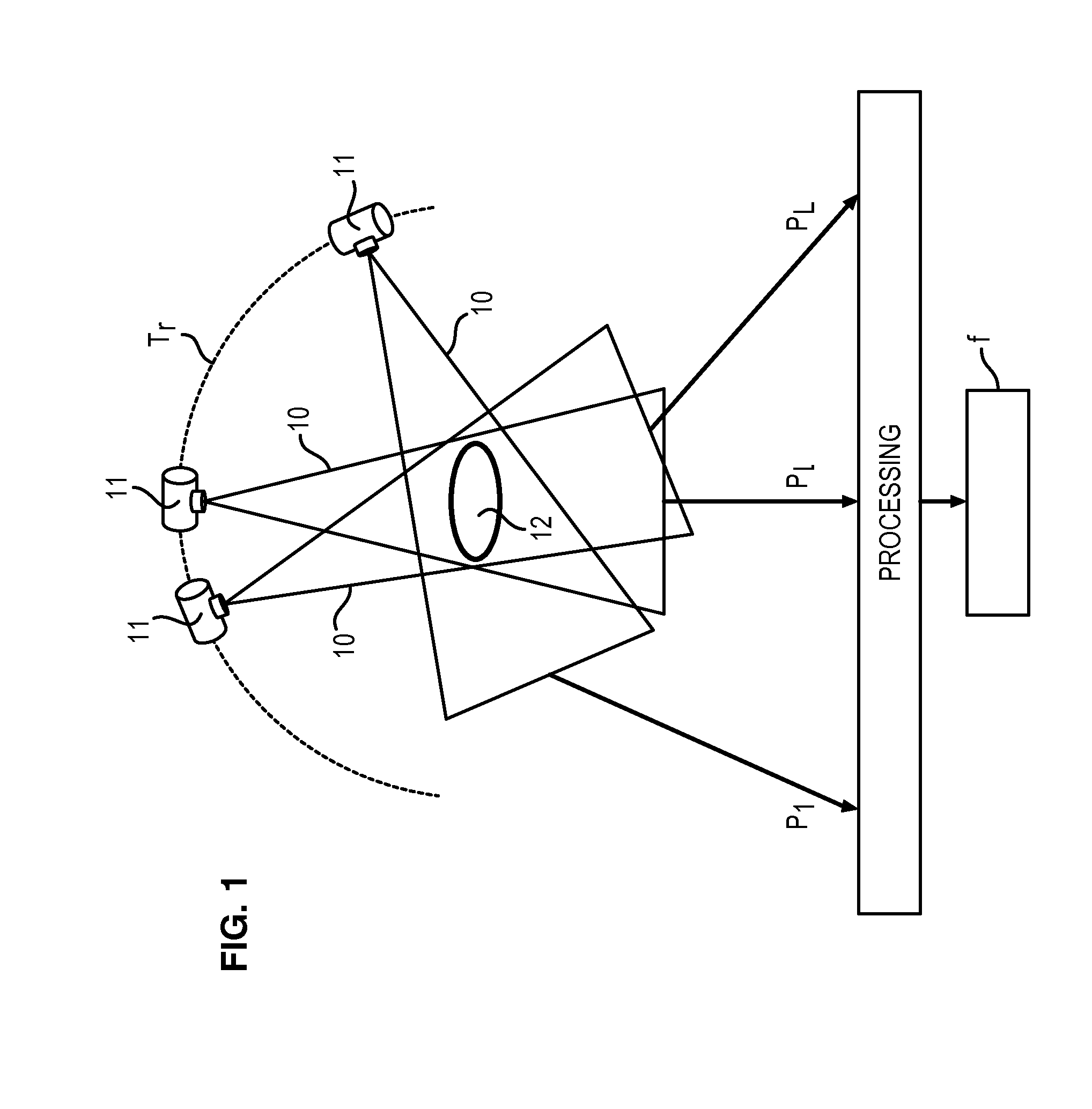
BACKGROUND OF THE INVENTION[0001]1. Field of the Invention[0002]In general, the field of the invention concerns tomographic reconstruction and more particularly the reconstruction of a sequence of 3D image(s) describing a moving object to be imaged.[0003]2. Description of Related Art[0004]Tomography allows images of an object to be obtained in the form of slices of a region of interest, by acquiring projections. FIG. 1 schematically illustrates the acquisition of 2D images of an object such as an organ, and the tomographic reconstruction of a 3D image of this organ. The reconstruction of a 3D image by tomography comprises the emission of X-rays 10 from a source towards the organ 12, the X-rays being emitted at different angles lε{1, . . . , L} which define the trajectory Tr of the source (commonly an angle of rotation). After passing through the organ 12, the X-rays 10 are detected by a detector (not illustrated) to form a set of 2D projections. There are as many 2D projections acqu...

Claims


Application Information

Patent Timeline
Patent Type & Authority Patents(United States)
IPC IPC(8): G06K9/00
CPCA61B6/548G06T11/006A61B6/032A61B6/5205G06T2211/412A61B6/4441G06T2211/436A61B6/486
Inventor RIDDELL, CYRILAUDIBERT, LORENZO
Owner GENERAL ELECTRIC CO
Learn More