
Irrigation system with multiple soil moisture based seasonal watering adjustment

a technology of irrigation system and seasonal watering schedule, which is applied in the direction of electric controllers, ignition automatic control, instruments, etc., can solve the problems of large amount of water wasted, increased complexity for users, and adjustment feature not producing the optimal watering schedul

Active Publication Date: 2014-07-29
HUNTER INDUSTRIES
View PDF138 Cites 83 Cited by
  • Summary
  • Abstract
  • Description
  • Claims
  • Application Information

AI Technical Summary

Benefits of technology

The present invention provides an irrigation controller with a memory and a processor for controlling multiple valves that deliver water to sprinklers in different zones. The controller includes a seasonal adjust feature that calculates the amount of water needed for each watering program and automatically adjusts the program based on the soil moisture level of each zone. This results in more efficient irrigation and saves water. Additionally, the invention includes a standalone soil moisture sensor control unit that communicates with the irrigation controller and adjusts the watering programs based on the soil moisture level in each zone.

Problems solved by technology

The problem with conventional irrigation controllers is that they are often set up to provide the maximum amount of irrigation required for the hottest and driest season, and then either left that way for the whole year, or in some cases the watering schedules are modified once or twice per year by the user.
The result is that large amounts of water are wasted.
While this allows for greater flexibility to perform better irrigation throughout the seasons, it adds to the complexity for the user.
The seasonal adjustment feature does not produce the optimum watering schedules because it does not take into consideration the amount of moisture that is actually available in the soil for the plants to utilize for healthy growth.
The problem is that most users do not re-set this on a regular basis, or do not set this correctly, so either a considerable amount of water is wasted, or turf and landscaping die.
When soil moisture sensors are used with conventional irrigation controllers the sensors typically interrupt the programmed irrigation cycle by breaking the electrical connection between the controller and the irrigation valves when the soil is moist.
While conventional soil moisture based controllers help to conserve water and maintain plant health over a wider range of weather conditions they are specifically adapted to soil moisture sensor control and may not meet other needs of the landscaped area well.
Soil moisture sensors that are hooked up to traditional irrigation controllers may simply disrupt the scheduled irrigation by disconnecting the common line to the valves when the soil is moist.
This can create confusion for the user when they go to the controller and see that station (X) is on yet they go out to the property to see that the same station is not running irrigation.
This can result in calls to professionals to debug the irrigation system when the soil moisture was just keeping the station from running as designed.
This requires a substantial cost in materials and labor.
When the sensors disrupt irrigation, while the controller thinks it is irrigating, the controller creates erroneous reports of over use of water, when in fact conservation is occurring.
When the theoretical and actual flow are not within certain parameters, an alarm will indicate that there is a problem with the irrigation system.
Soil moisture installations mentioned above will not work with these types of controllers.
This requires abnormal programming in the controller and also requires the soil moisture sensor to be placed in the last station to be run so the irrigation does not shut off before all stations have irrigated.
With this arrangement, watering conservation may not be optimized as all of the previous stations may have run too much water for proper irrigation to have occurred prior to the last station sensing that the soil is moist after just a few minutes of irrigation.

Method used


Image

  • Irrigation system with multiple soil moisture based seasonal watering adjustment
  • Irrigation system with multiple soil moisture based seasonal watering adjustment
  • Irrigation system with multiple soil moisture based seasonal watering adjustment

Examples


first embodiment

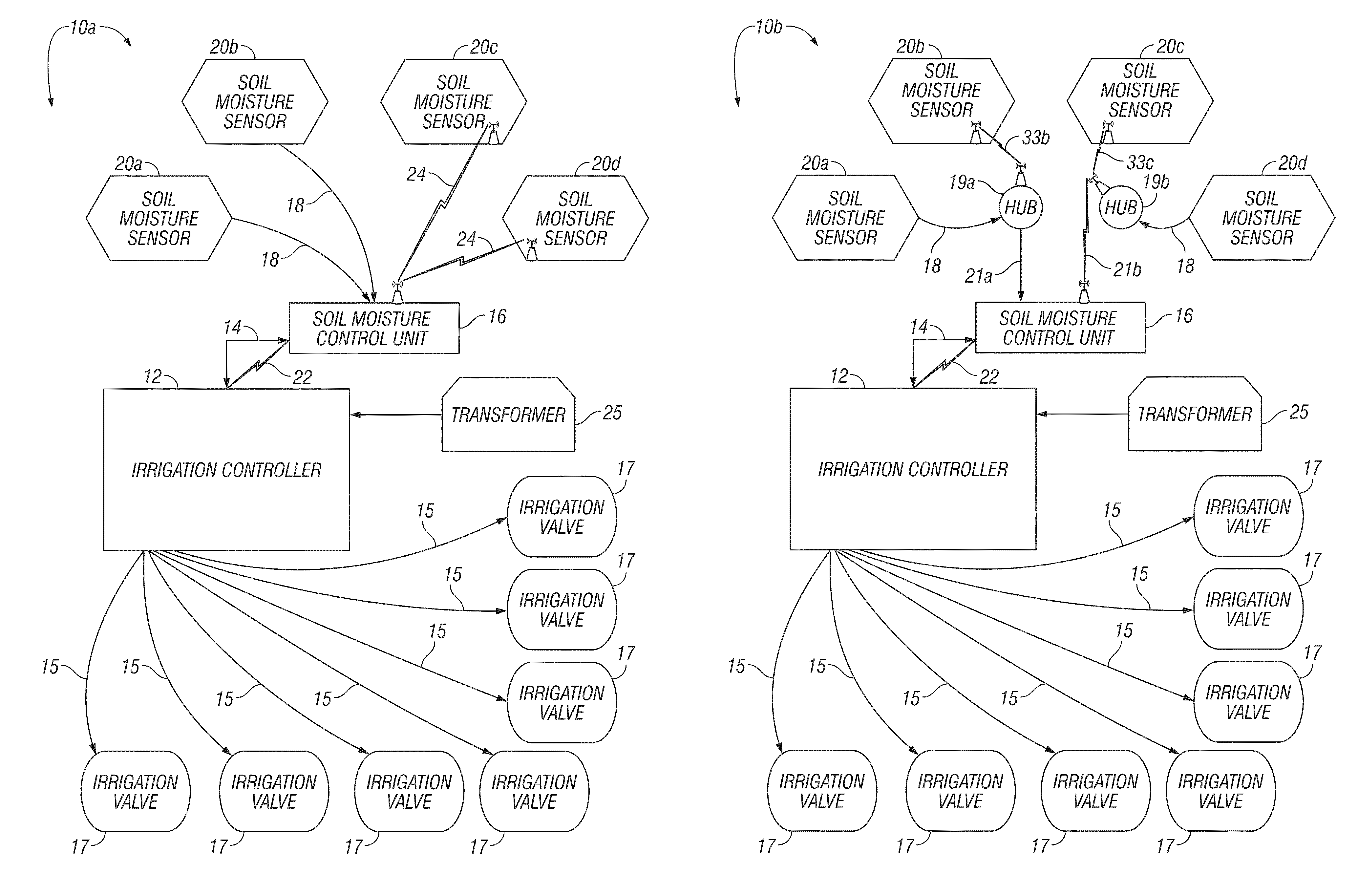
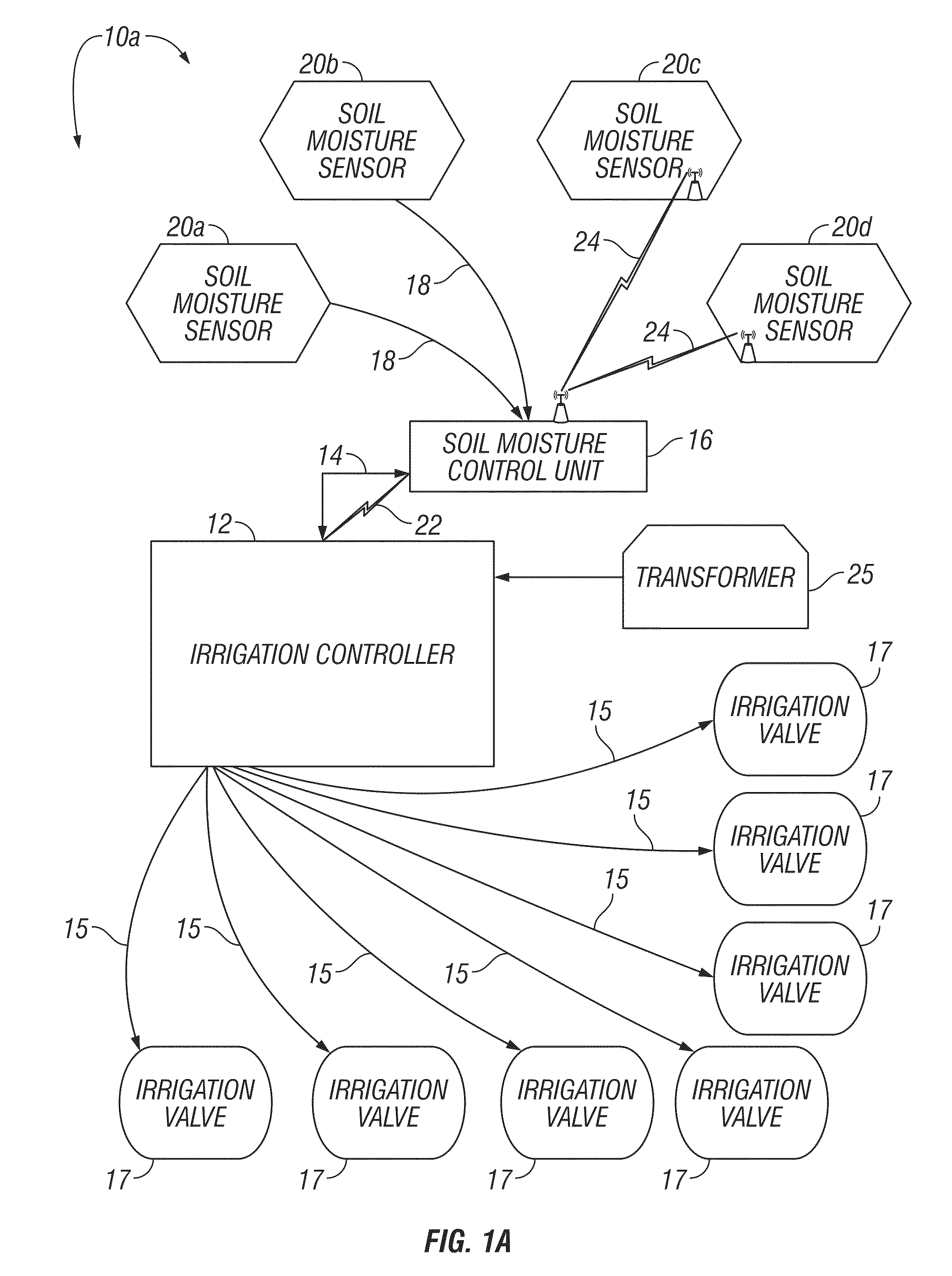
[0043]Referring to FIG. 1A, in accordance with the present invention, an irrigation system 10a comprises a stand alone irrigation controller 12 connected via cable 14 to a stand alone soil moisture control unit 16 that is in turn connected via buried multi-wire cables 18 to a plurality of soil moisture sensors 20a-20b. It will be understood that the many advantages of the present invention can be achieved with a single soil moisture sensor, however, multiple soil moisture sensors are preferred. FIG. 1A illustrates various means for communication between the soil moisture sensors 20a-d and the soil moisture sensor control unit 16. The controller 12, soil moisture unit 16 and one or more soil moisture sensors 20c and 20d exchange data and commands via wireless communication links 22 and 24.

[0044]The stand alone irrigation controller 12 (FIG. 1A) and soil moisture control unit 16 would typically be mounted in a garage or other protected location, although they can have a waterproof con...

second embodiment

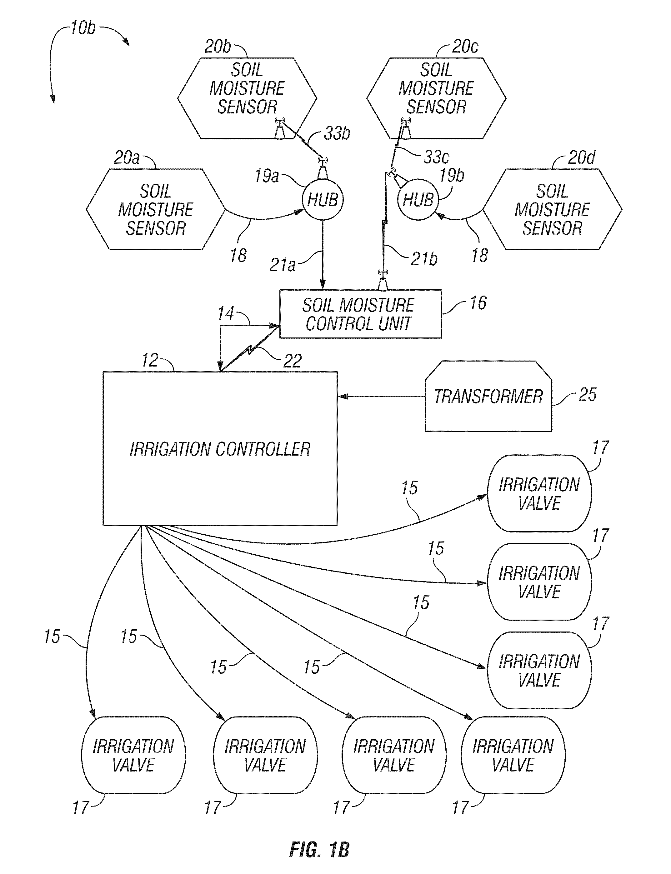
[0046]Referring to FIG. 1B, in accordance with an the present invention, an irrigation system 10b comprises a stand alone irrigation controller 12 connected via cable 14 to a stand alone soil moisture control unit 16. This figure illustrates alternate means for communication to and from the soil moisture sensors 20a-d and the soil moisture sensor control unit 16 through communications hubs 19(a-b). Soil moisture control unit 16 is connected via cable 21a to a communications hub 19a. Communications hub 19a is connected to soil moisture sensor 20a using cable 18 and wireless connection 33b is used to communicate with soil moisture sensor 20b. Soil moisture sensors 20c and 20d communicate with communications hub 19b using wireless connection 33c and cable 18 respectively. Communications hub 19b communicates through wireless link 21b to the soil moisture control unit 16. The controller 12 and soil moisture control unit 16 would typically be mounted in a garage or other protected locatio...

third embodiment

[0048]Referring to FIG. 1C, in accordance with the present invention, an irrigation system 10c comprises a standalone irrigation controller 12 connected via cable 14 to a standalone soil moisture control unit 16 that is in turn connected via a multi wire cable 23 to one or more decoder modules 24. Each soil moisture sensor 20a-d is connected to a decoder module 29 via sensor wiring 18. Optionally, the decoder module 29 may be built into the housings of the soil moisture sensors 20a-d to allow connection directly to cable 23. The controller 12 and soil moisture control unit 16 would typically be mounted in a garage or other protected location, although they can have a waterproof construction that allows them to be mounted out of doors.

[0049]In the third embodiment 10c the soil moisture sensors 20a-d are typically mounted in the ground at places that represent the typical moisture content of the irrigated areas. The cables 14 and 18 typically include copper wires so that power can be ...


PUM


Abstract

An irrigation controller has a control panel including a display and a plurality of user inputs. A processor is operatively connected to the control panel and to a memory. A plurality of switches are operatively connected to the processor for turning a power signal ON and OFF to a plurality of valves that deliver water to a plurality of sprinklers in different zones. Programming is stored in the memory for implementing a seasonal adjustment feature that is independently operable with a plurality of individual watering programs to selectively energize the valves. The programming calculates a soil moisture requirement value for each program using a signal from at least one soil moisture sensor that is associated with a zone that is assigned to that watering program, and automatically modifies the watering program assigned to that zone through the seasonal adjust feature based on the soil moisture requirement value.

Description

CROSS-REFERENCE TO RELATED APPLICATIONS[0001]This application is related, by inventorship and subject matter, to co-pending U.S. patent application Ser. No. 12 / 251,179 filed Oct. 14, 2008 by Peter J. Woytowitz et al. entitled “Irrigation System with Soil Moisture Based Seasonal Watering Adjustment.” This application claims priority from the similarly entitled U.S. Provisional Application Ser. No. 61 / 156,397 filed by Peter J. Woytowitz et al. on Feb. 27, 2009.FIELD OF THE INVENTION[0002]The present invention relates to residential and commercial irrigation systems, and more particularly to irrigation controllers that use soil moisture data in calculating and executing watering schedules.BACKGROUND OF THE INVENTION[0003]Electronic irrigation controllers have long been used on residential and commercial sites to water turf and landscaping. They typically comprise a plastic housing that encloses circuitry including a processor that executes a watering program. Watering schedules are typ...

Claims


Application Information

Patent Timeline
Patent Type & Authority Patents(United States)
IPC IPC(8): G05D11/00F16K31/00B05B3/00G05B11/01
CPCG05B11/01B05B3/00F16K31/00G05D11/00B05B12/02A01G25/167B05B12/12Y10T137/1866
Inventor WOYTOWITZ, PETER J.KREMICKI, JEFFREY J.PORTER, LAMONTE D.
Owner HUNTER INDUSTRIES
Learn More